

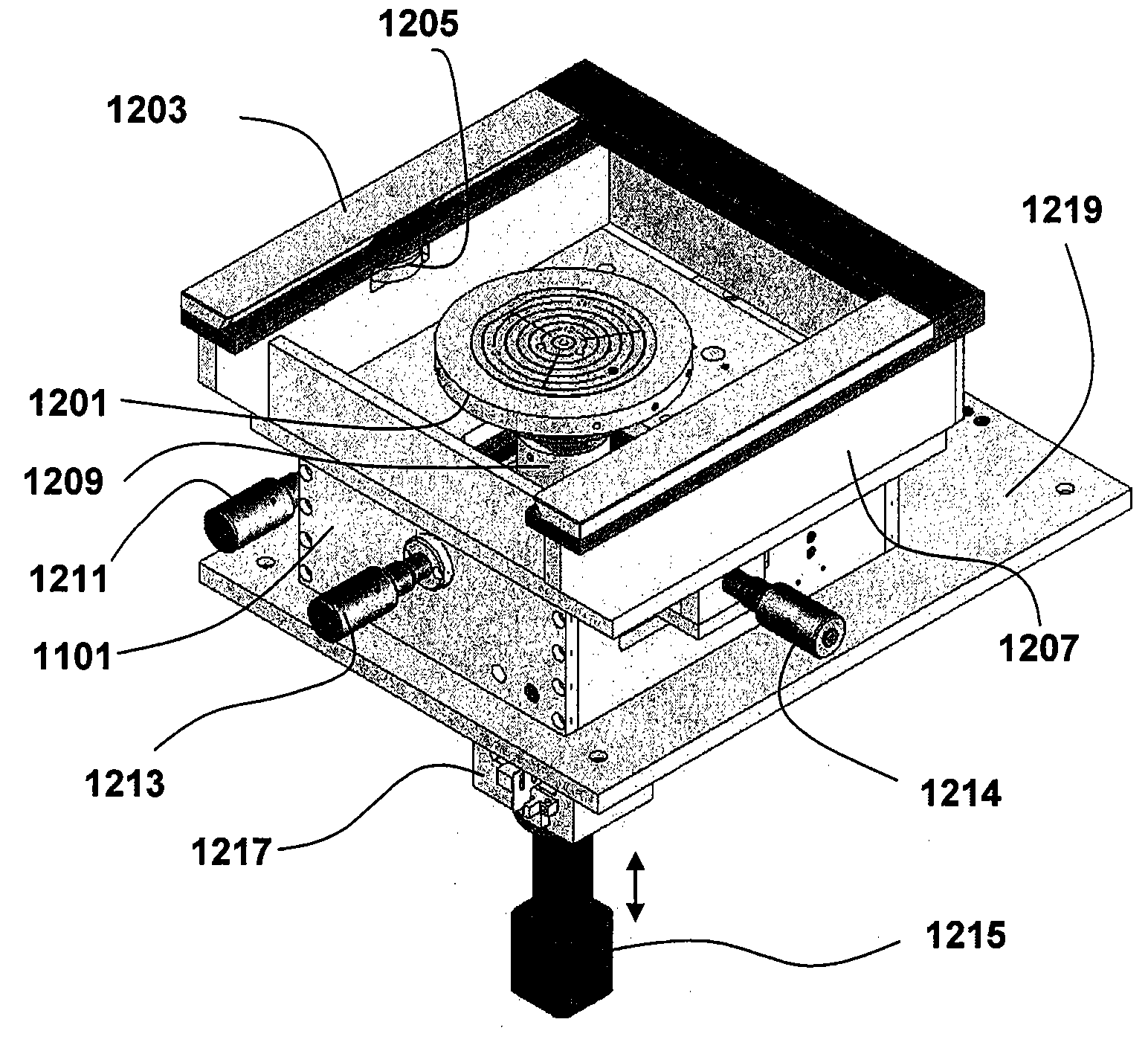
Align-transfer-imprint system for imprint lithogrphy
a technology of aligning transfer and imprint, applied in the field of system for imprint lithography, can solve the problems of increasing the cost of equipping and operating optical stepper technology, reducing the attainable resolution of step-and-repeat optical lithography, and increasing the cost of small businesses to achieve the effect of enhancing surface adhesion and enhancing surface adhesion
- Summary
- Abstract
- Description
- Claims
- Application Information
AI Technical Summary
Benefits of technology
Problems solved by technology
Method used
Image

Examples
Embodiment Construction
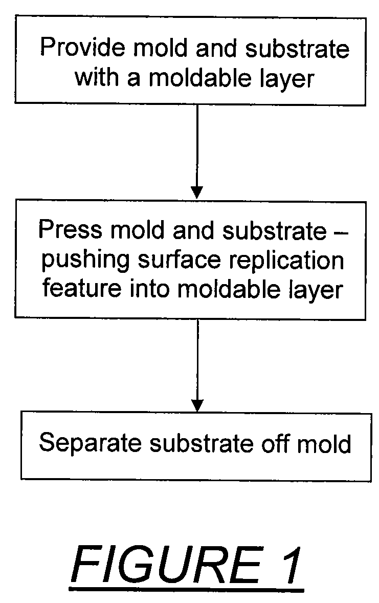
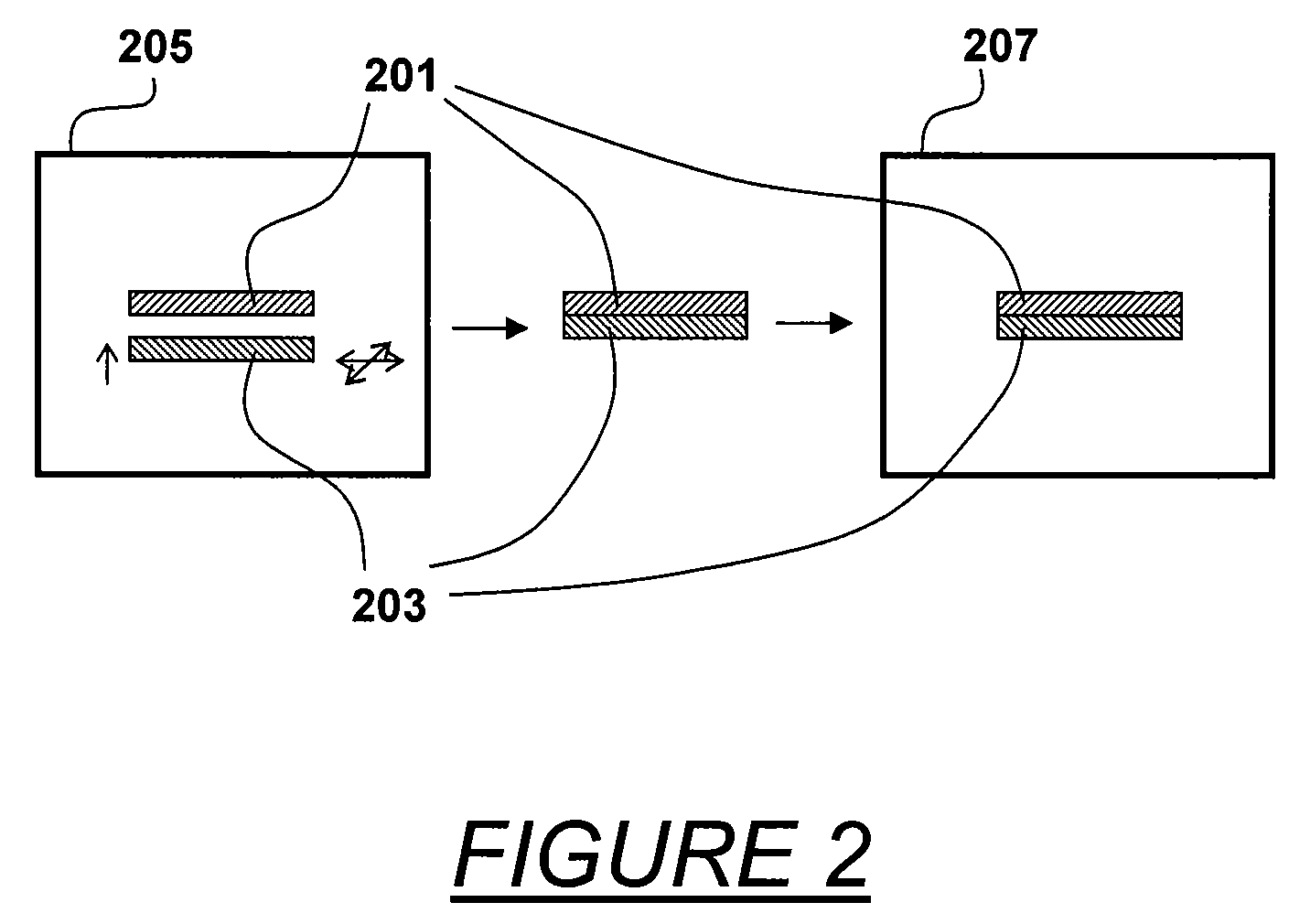
[0037]Imprint lithography is particularly useful in the replication of patterns having microscale and nanoscale features. Imprint lithography can be divided into thermal imprint lithography and UV (ultraviolet light) imprint lithography. Thermal imprint lithography uses a thermal plastic polymer or a thermal curable polymer as a resist. UV imprint lithography uses a UV curable polymer as resist. In thermal imprint lithography, the polymer is heated to a flowing condition before or during imprinting and permitted to cool to retain the imprint. In UV imprint lithography, the polymer is applied as a liquid, imprinted and then cured by UV exposure to retain the imprint.
[0038]Generally, the substrate and the mold are prepared prior to imprinting. A moldable polymer layer is applied on the substrate as by spinning, dropping or deposition. The mold is provided with a topological surface variation (projecting and recessed features) that are to be imprinted into the moldable polymer. A thin ...
PUM
| Property | Measurement | Unit |
|---|---|---|
| wavelength | aaaaa | aaaaa |
| size | aaaaa | aaaaa |
| moldable | aaaaa | aaaaa |
Abstract
Description
Claims
Application Information