
Solar Cell Module

a solar cell and module technology, applied in the field of solar cell modules, can solve the problems of reducing the power generation capability the variation of the film thickness and composition of the precursor, and the light absorption layer and the transparent second electrode layer, so as to achieve the conversion efficiency of the overall solar cell module, excellent power generation characteristics, and improved power generation capability

Inactive Publication Date: 2008-09-11
HONDA MOTOR CO LTD
View PDF2 Cites 44 Cited by
  • Summary
  • Abstract
  • Description
  • Claims
  • Application Information

AI Technical Summary

Benefits of technology

[0011]It may be proposed to increase the amounts of generated currents of those solar cells which are positioned at the ends of the solar cell module in order to increase the power generating capability of the solar cell module. To realize the proposal, variations of the film thicknesses and compositions of a precursor which will be processed into the light absorption layer and the transparent second electrode layer may be reduced when solar cells are fabricated, because different film thicknesses and compositions of those layers adversely affect the amount of generated currents.
[0012]It may also be proposed to reduce variations of a temperature distribution in a seleniding furnace during a process of seleniding the precursor for producing the light absorption layer, or to reduce the difference between the flowing speeds, respectively at central and end portions of the glass substrate, of a solution used in a chemical bath bonding (CBD) process for forming the buffer layer.
[0013]However, if the solar cell module is large in size, then since the glass substrate is also large in size, it is difficult to reduce the variations of the film thicknesses and compositions of the precursor and the second electrode layer by sputtering, to reduce the variations of the temperature distribution in the seleniding furnace, and to reduce the difference between the flowing speeds, respectively at the central and end portions of the glass-substrate, of the solution used in the CBD process.
[0016]A major object of the present invention is to provide a solar cell module which is large in size and yet exhibits an excellent power generating capability.
[0018]According to the present invention, therefore, there are solar cells having different cell areas. The different cell areas make it possible to substantially uniformize the amounts of generated currents of the solar cells.
[0019]According to the present invention, those solar cells which would have smaller amounts of generated currents if electricity were generated by a solar cell module made up of solar cells having identical areas, are constructed as solar cells having larger cell areas to increase amounts of generated currents thereof, so that the amounts of generated currents of the solar cells are made substantially uniform. As a result, the conversion efficiency of the overall solar cell module is increased. The power generating capability of the overall solar cell module is thus increased. Stated otherwise, there is provided a solar cell module of excellent power generating characteristics.

Problems solved by technology

If the amounts of generated currents of these solar cells are small, then the power generating capability of the overall solar cell module is not sufficiently large even though the amounts of generated currents of the other solar cells are large.
To realize the proposal, variations of the film thicknesses and compositions of a precursor which will be processed into the light absorption layer and the transparent second electrode layer may be reduced when solar cells are fabricated, because different film thicknesses and compositions of those layers adversely affect the amount of generated currents.

Method used


Image

  • Solar Cell Module
  • Solar Cell Module
  • Solar Cell Module

Examples


Embodiment Construction

[0029]Solar cell modules according to preferred embodiments of the present invention will be described in detail below with reference to the accompanying drawings.

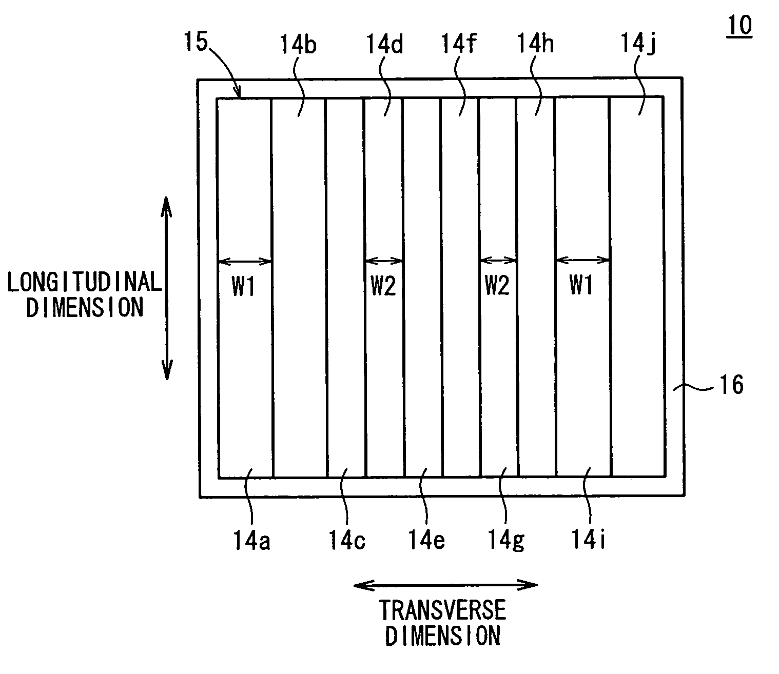
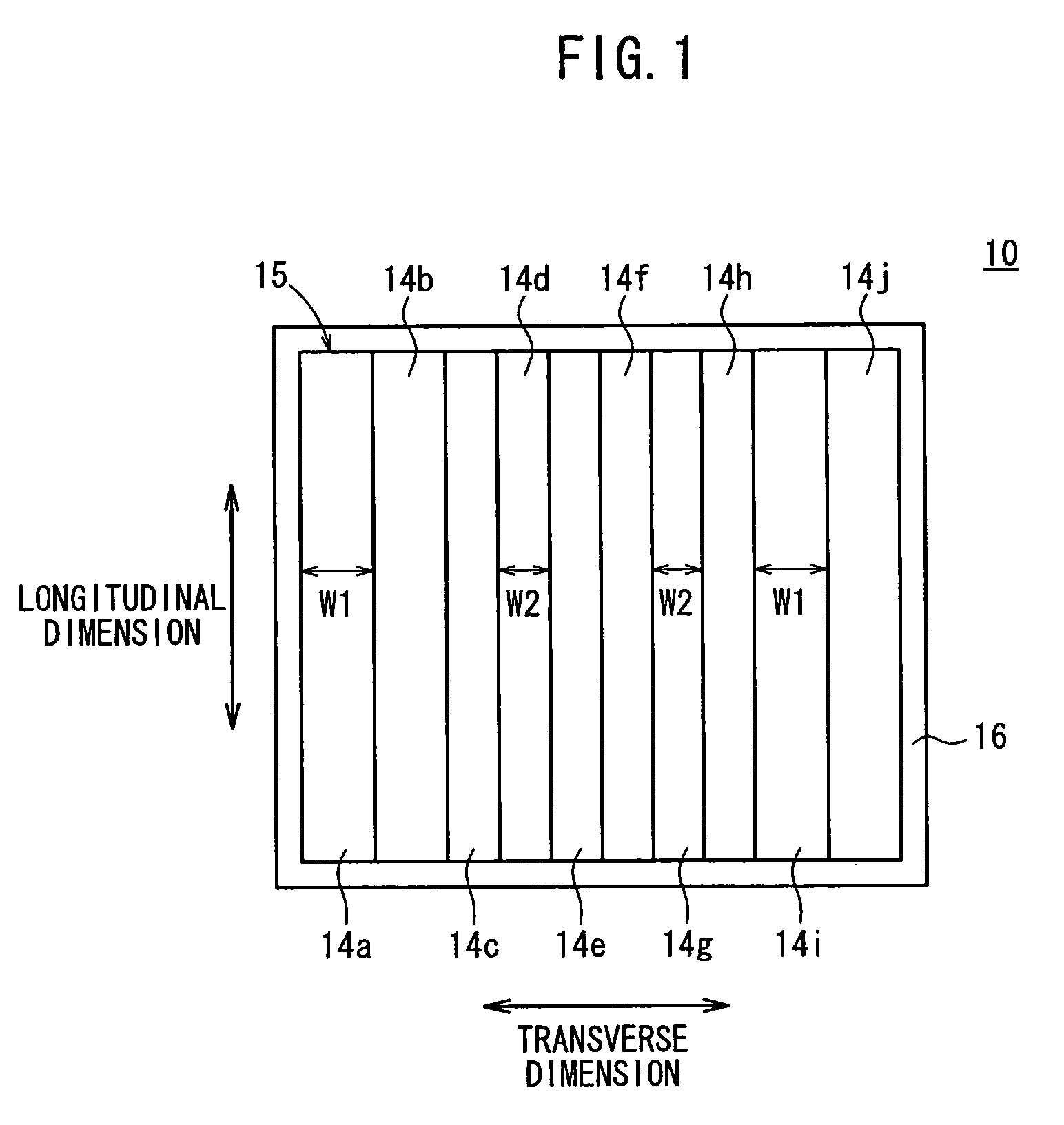
[0030]FIG. 1 is a schematic plan view of a solar cell module according to an embodiment of the present invention. The solar cell module 10 comprises a cell unit 15 made up of an array of ten adjacent solar cells 14a through 10f and housed in a casing 16. The casing 16 is filled with a molded mass of resin, not shown, protecting the solar cells 14a through 14j.

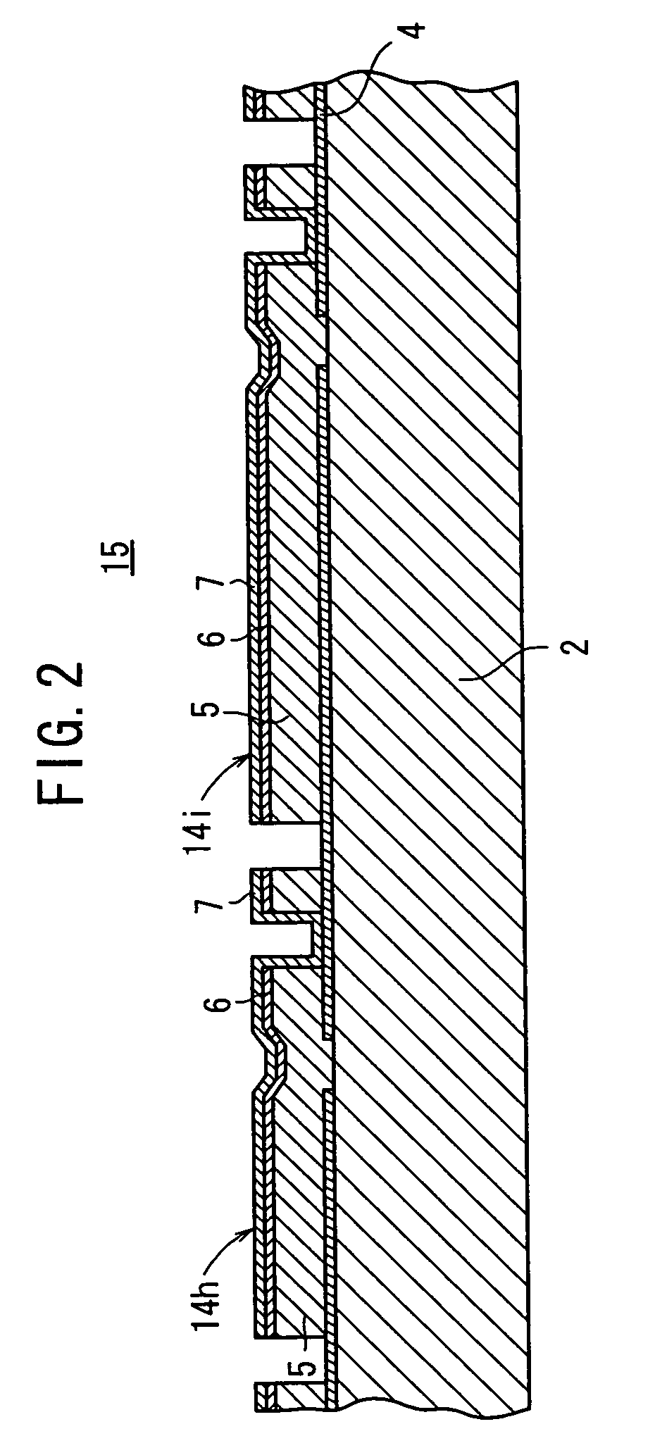
[0031]FIG. 2 shows the solar cells 14h, 14i in enlarged fragmentary transverse cross section. The transverse structure of the cell unit 15 is substantially the same as the cell unit 3 shown in FIG. 5. Specifically, the cell unit 15 has the solar cells 14a through 14j monolithically disposed on a single glass substrate 2. Each of the solar cells 14a through 14j comprises, for example, a first electrode layer 4 made of Mo, a light absorption layer 5 made of CIGS, a buf...


PUM


Abstract

Disclosed is a solar cell module comprising ten solar cells. The widths W1 of the solar cells arranged on the ends and the solar cells respectively arranged next to the solar cells are set 10-25% (1.1-1.25 times) longer than the widths W2 of the other solar cells. Consequently, the cell areas of the solar cells are larger than the cell areas of the other solar cells.

Description

TECHNICAL FIELD[0001]The present invention relates to a solar cell module comprising a cell unit made up of a plurality of solar cells disposed on a single substrate.BACKGROUND ART[0002]Chalcopyrite solar cells are solar cells having a chalcopyrite compound (hereinafter referred to as “CIGS”) represented as Cu(InGa)Se as a light absorption layer. Much attention has been paid to chalcopyrite solar cells because they have many advantages, e.g., they have a high energy conversion efficiency, are almost free of light-induced degradation due to aging, are of excellent radiation resistance, have a wide light absorption wavelength range, and have a large light absorption coefficient.[0003]As shown in FIG. 5, a plurality of chalcopyrite solar cells 1 of the type described are monolithically disposed on a single glass substrate 2, providing a cell unit 3. Each of the chalcopyrite solar cells 1 comprises, for example, a first electrode layer 4 made of Mo, a light absorption layer 5 made of CI...

Claims


Application Information

Patent Timeline
IPC IPC(8): H01L31/04
CPCH01L31/042H01L31/046Y02E10/50Y02E10/541Y02P70/50
Inventor IWAKURA, TADASHI
Owner HONDA MOTOR CO LTD
Learn More