Systems and methods for a gas field ionization source

a technology of gas field ionization and gas field, which is applied in the field of atomic level ion sources, can solve the problems of unstable and unreliable prior efforts to utilize ion sources for imaging applications, and achieve the effects of increasing the temperature of the emitter, increasing the mobility of atoms, and accelerating the rearrangement of crystal structures

Active Publication Date: 2008-09-11
CARL ZEISS MICROSCOPY GMBH
View PDF115 Cites 79 Cited by
  • Summary
  • Abstract
  • Description
  • Claims
  • Application Information

AI Technical Summary

Benefits of technology

[0007]In one aspect the invention provides a gas field ion source assembly that includes an ion source in connection with an optical column, such that an ion beam generated at the ion source travels through the optical column. The ion source includes an emitter having a width that tapers to a tip comprising a few atoms. In other aspects, the invention provides methods for manufacturing, maintaining and enhancing the performance of a gas field ion source including sharpening the tip of the ion source in situ.
[0020]In one embodiment, the crystal structure may be rearranged by at least increasing the temperature of the emitter and thereby increasing the mobility of atoms near the atomic shelf. The crystal structure may also be rearranged by applying a voltage to the emitter. In certain embodiments, the crystal structure may be rearranged in the presence of adsorbed atoms near the distal end of the emitter. In such embodiments, the adsorbed atoms may include at least one of oxygen, palladium and platinum. The adsorbed atoms may accelerate the rearrangement of the crystal structure.

Problems solved by technology

However, prior efforts to utilize ion sources for imaging applications haven proven to be unstable and unreliable.

Method used


Image

  • Systems and methods for a gas field ionization source
  • Systems and methods for a gas field ionization source
  • Systems and methods for a gas field ionization source

Examples


Embodiment Construction

[0049]There are other aspects and embodiments of the systems and methods of the invention will be described more fully by referring to the figures provided.

[0050]The systems and methods described herein will now be described with reference to certain illustrative embodiments. However, the invention is not to be limited to these illustrated embodiments which are provided merely for the purpose of describing the systems and methods of the invention and are not to be understood as limiting in anyway.

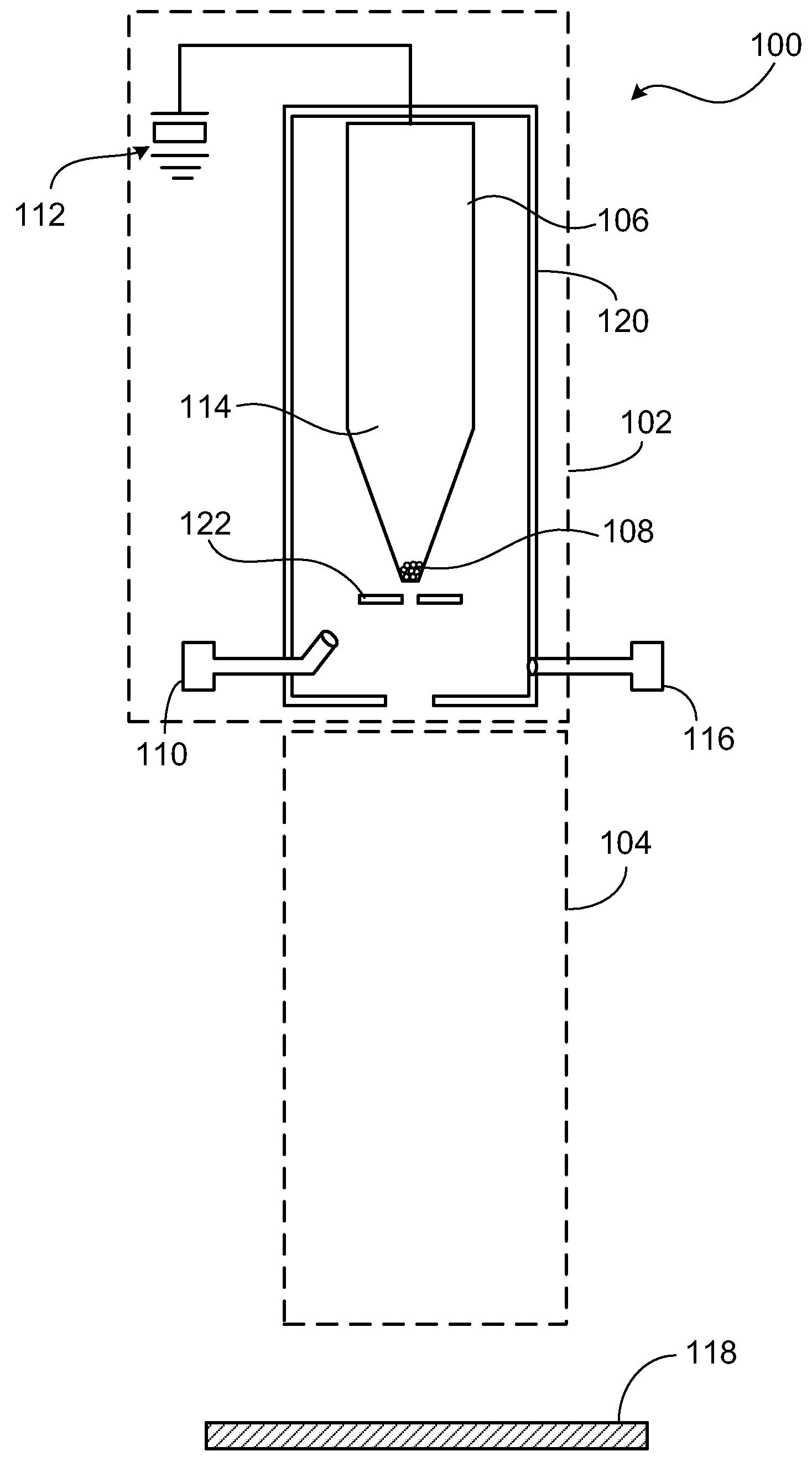
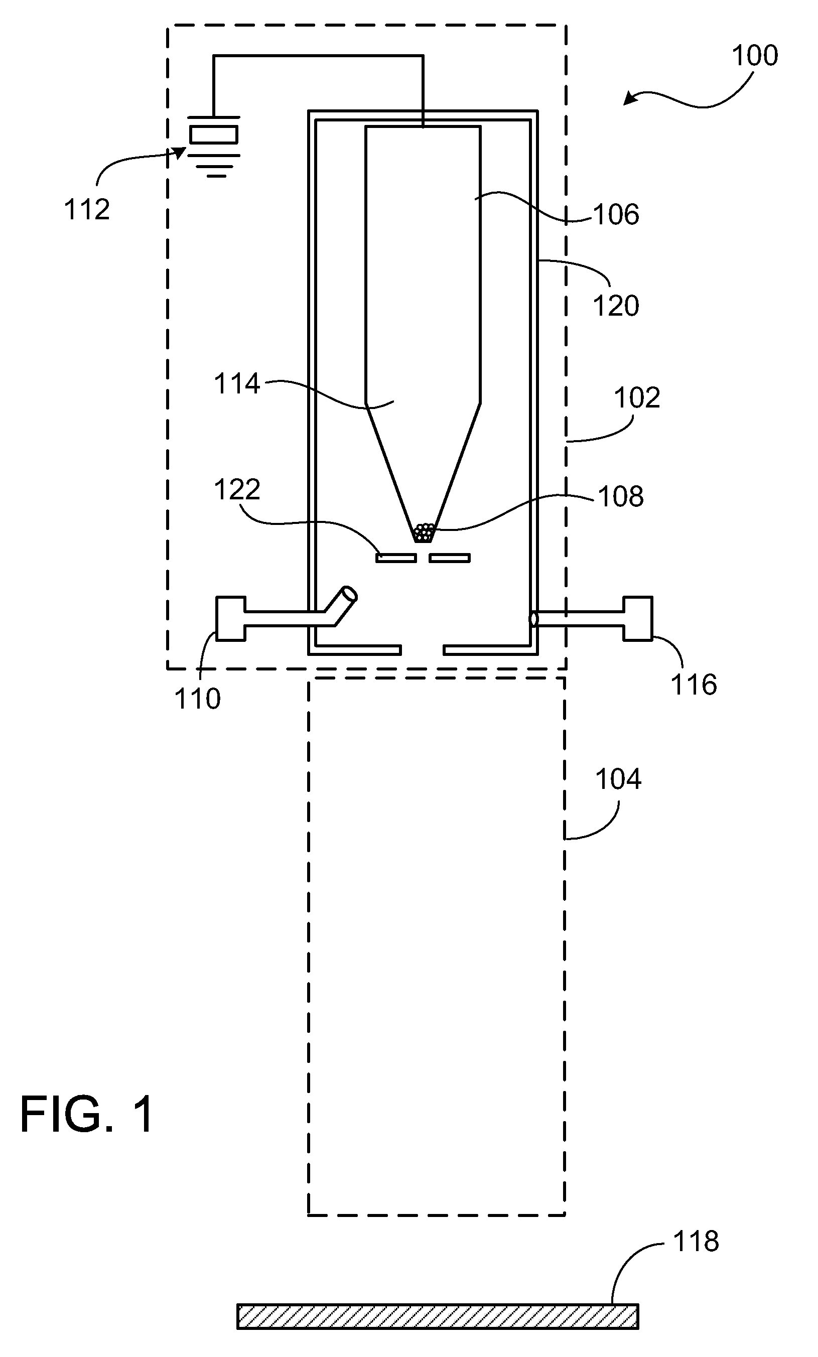
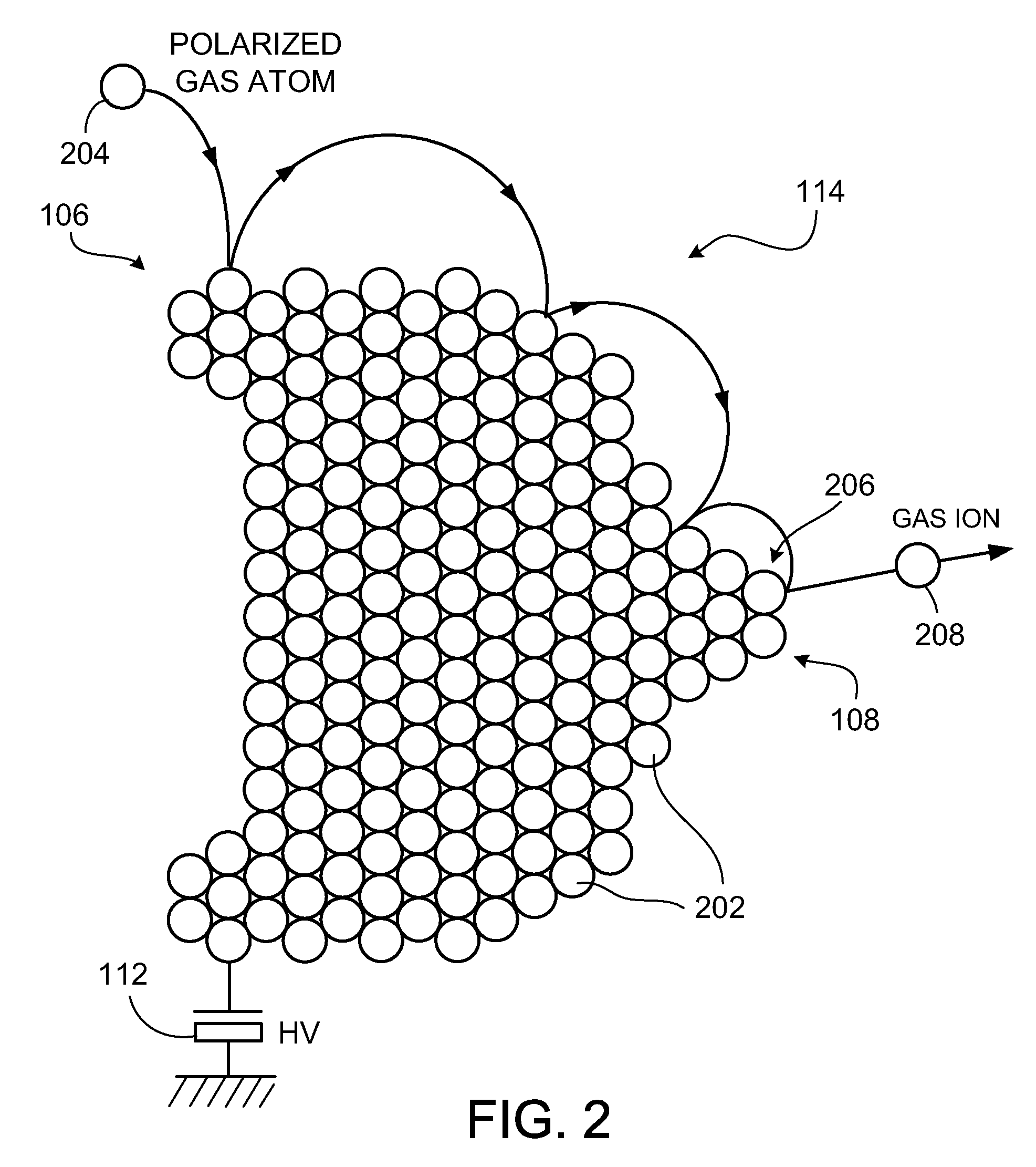
[0051]As will be seen from the following description, in one aspect the invention provides a gas field ion source assembly that includes an ion source in connection with an optical column, such that an ion beam generated at the ion source travels through the optical column. The ion source includes an emitter having a width that tapers to a tip comprising a few atoms. In other aspects, the invention provides methods for manufacturing, maintaining and enhancing the performance of a gas field ...


PUM


Abstract

In one aspect the invention provides a gas field ion source assembly that includes an ion source in connection with an optical column such that an ion beam generated at the ion source travels through the optical column. The ion source includes an emitter having a width that tapers to a tip comprising a few atoms. In other aspects, the methods provide for manufacturing, maintaining and enhancing the performance of a gas field ion source including sharpening the tip of the ion source in situ.

Description

CROSS REFERENCE TO RELATED APPLICATIONS[0001]This application claims priority under 35 U.S.C. § 120 to, and is a continuation-in-part of, U.S. Ser. No. 10 / 966,243, filed Oct. 15, 2004, which in turn claims priority under 35 U.S.C. § 119 to U.S. Ser. No. 60 / 511,726, filed Oct. 16, 2003.[0002]This application also claims priority under 35 U.S.C. § 120 to, and is a continuation-in-part of, U.S. Ser. No. 11 / 385,136, filed Mar. 20, 2006.FIELD OF INVENTION[0003]This invention relates to an ion source and more particularly to an atomic level ion source (ALIS) generating ions from a volume near the size of a single atom.BACKGROUND[0004]Charged particle microscopes typically use electrons or metal ions. Both types of microscopes are moderately reliable, and the electron microscope provides very high resolution. However, helium ion microscopes have certain advantages over the electron microscope. Light ions significantly reduce the optical diffraction effects that electrons cause and they hav...

Claims


Application Information

Patent Timeline
Patent Type & Authority Applications(United States)
IPC IPC(8): H01J27/26
CPCH01J27/26H01J37/08H01J2237/28H01J2237/065H01J2237/0807H01J2237/06341
Inventor WARD, BILLY W.FARKAS, LOUNOTTE, JOHN A.PERCIVAL, RANDALL
Owner CARL ZEISS MICROSCOPY GMBH
Why Eureka
Try Eureka