Light emitting diode (LED) based lighting systems

a technology of light emitting diodes and lighting systems, applied in lighting support devices, lighting and heating apparatuses, with built-in power, etc., can solve the problems of limited system design of led lighting fixtures, achieve easy fabrication, increase the intensity of output light, and dissipate heat generated by excitation sources

Active Publication Date: 2008-09-11
INTEMATIX
View PDF15 Cites 70 Cited by
  • Summary
  • Abstract
  • Description
  • Claims
  • Application Information

AI Technical Summary

Benefits of technology

[0008]In the context of the present invention the shade is located remotely to the excitation source and is configured such that excitation energy travels, propagates in free-space (that is it is not guided by an optical medium), a distance of at least one centimeter from the excitation source to the shade.
[0009]The at least one phosphor can be provided on at least a part of an inner surface of the shade. Alternatively, or in addition, the at least one phosphor can be provided on at least a part of an outer surface of the shade. In a further embodiment, the at least one phosphor is incorporated within at least a part of the shade. Incorporating the phosphor as an integral part of the shade eases fabrication where the shade is fabricated of a plastics material.
[0010]In a another implementation the phosphor can be incorporated in a flexible sheet material which can then be applied to on inserted inside the shade.
[0011]The lighting system can further comprise providing first and second phosphors. Such an arrangement enables different colors of light to be generated for radiation passing through the shade and that passing out an opening in the shade. The first and second phosphors can comprise respective layers or be provided as a mixture in at least one layer or be incorporated as a mixture within the shade.
[0012]The excitation source preferably comprises a light emitting diode or a plurality of light emitting diodes. Preferably the LED / s is / are operable to emit radiation of wavelength in a range 300 to 500 nm that is U.V. to blue light.
[0013]In another arrangement the lighting system further comprises a reflector configured to reflect excitation radiation towards the at least one phosphor. A reflector increases the intensity of the output light and in the case of a system which utilizes a U.V. radiation source provides protection against damage to the human eye. To dissipate heat generated by the excitation source the lighting system further comprises heat sinking means in thermal communication with the excitation source. In a one arrangement the heat sinking means is fabricated as a part of the lighting fixture.

Problems solved by technology

Today, lighting fixture designs utilizing LEDs are limited to systems in which an LED (or an array of LEDs), replaces conventional light sources such as incandescent bulbs and fluorescent lamps.

Method used


Image

  • Light emitting diode (LED) based lighting systems
  • Light emitting diode (LED) based lighting systems
  • Light emitting diode (LED) based lighting systems

Examples


Embodiment Construction

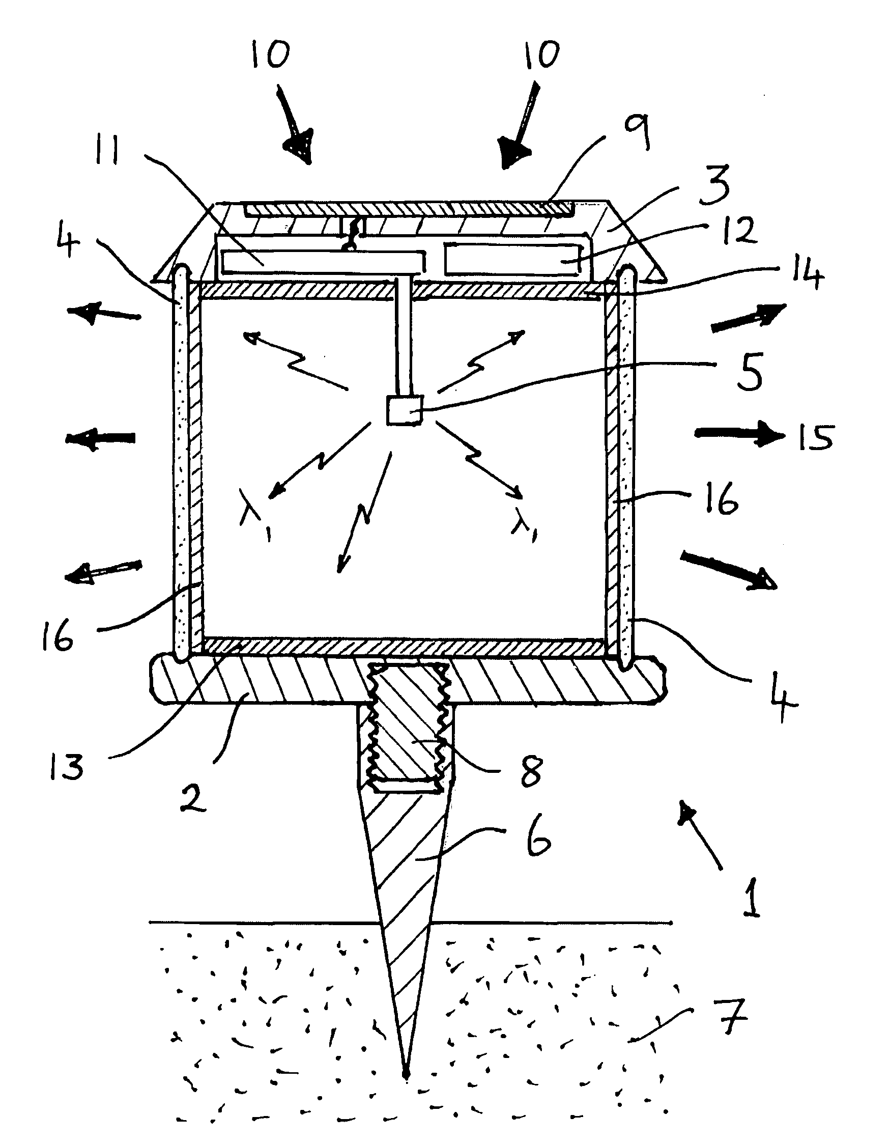
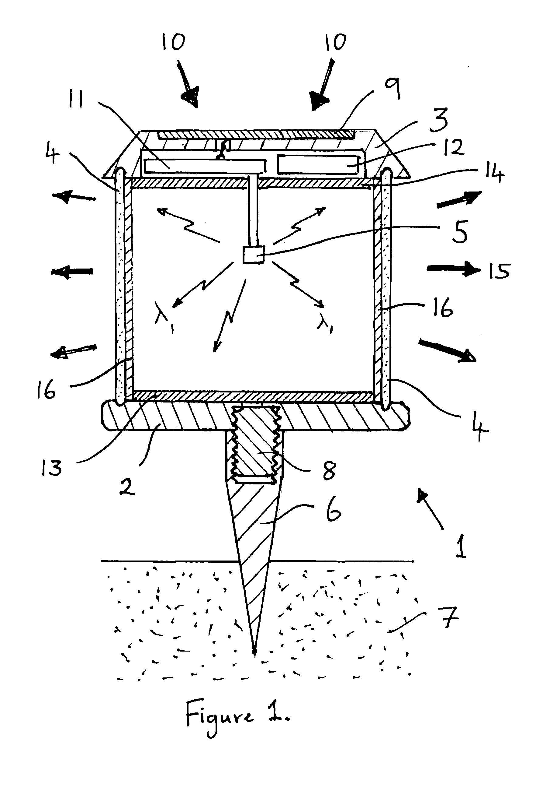
[0028]Referring to FIG. 1 there is shown a schematic cross-sectional representation of a lighting system in accordance with the present invention which comprises an outdoor lighting fixture or solar powered garden lantern 1. The lantern 1 is generally cylindrical in form and comprises a circular base 2, a circular top 3, a translucent hollow cylindrical shade 4 disposed between the base and top and a radiation source 5 mounted within the volume defined by the shade 4 in conjunction with the base 2 and top 3. A spike 6 is secured to on an underside of the base 2 enabling the lantern 1 to be installed by inserting the spike 6 into the ground 7. In the embodiment illustrated the spike 6 is removeably secured to the base 2 by a threaded stud 8 enabling the lantern 1 to be secured to fixtures other than the spike such as a wall bracket etc.

[0029]In an outer surface of the top 3 there is provided a solar cell, photovoltaic cell, 9 for operating the lantern from incident ambient light 10. ...


PUM

PropertyMeasurementUnit
distanceaaaaaaaaaa
wavelengthaaaaaaaaaa
excitation radiation of wavelengthaaaaaaaaaa

Abstract

A lighting system comprises at least one excitation source (5), preferably an LED, operable to generate and radiate excitation radiation of a first wavelength (λ1); a shade (4) configured to at least in part surround the at least one source (5) and remotely located thereto; and at least one phosphor (16) provided in or on at least a part of the shade (4), wherein the phosphor (16) emits radiation of a different wavelength in response to incident excitation radiation. The phosphor can be provided on a part of an outer or inner surface of the shade. Alternatively, or in addition, the phosphor is incorporated within the shade. The lighting system finds particular application as a hanging, a desk, a floor standing, a wall mountable, a spot, an outdoor or an accent lighting fixture.

Description

BACKGROUND OF THE INVENTION[0001]1. Field of the Invention[0002]The invention relates to light emitting diode based lighting systems and in particular to systems in which a phosphor (photo luminescent) material is utilized to generate a desired color of light.[0003]2. Description of the Related Art[0004]The introduction of the solid-state semiconductor devices such as semiconductor light emitting diodes (LEDs) has allowed a new generation of lighting systems to come into existence. Today, lighting fixture designs utilizing LEDs are limited to systems in which an LED (or an array of LEDs), replaces conventional light sources such as incandescent bulbs and fluorescent lamps. As is known with conventional lighting sources a lamp or light shade is used to prevent direct viewing of the light source and for aesthetic considerations. Often the shade is made from a translucent material, such as card, woven material or a plastics material, or from glass. Moreover, the shade can be made of a ...

Claims


Application Information

Patent Timeline
Patent Type & Authority Applications(United States)
IPC IPC(8): F21V9/16F21V9/40
CPCF21S8/033F21S8/06F21V1/00F21V1/16F21V3/0481F21V21/0824F21Y2101/02Y10S362/80F21K9/56F21V9/16F21S9/037F21V13/08F21W2131/103F21Y2105/10F21Y2115/10F21V1/17F21V3/08F21V3/12F21V9/32Y02B20/72F21V9/30
Inventor LI, YI-QUN
Owner INTEMATIX
Why Eureka
Try Eureka