Cylindrical Steam Reformer Having Integrated Heat Exchanger

a technology of integrated heat exchanger and cylindrical steam, which is applied in the field of cylindrical steam reformer, can solve the problems of low efficiency, complicated manufacture of such a reactor, and technical and commercial limitations of hydrogen production from alternative energy as pure clean energy, and achieve the optimal performance of individual parts, minimize the necessary capacity of an additional external heat exchanger, and optimize the heat exchange network

Inactive Publication Date: 2008-09-11
SK ENERGY CO LTD (KR)
View PDF4 Cites 7 Cited by
  • Summary
  • Abstract
  • Description
  • Claims
  • Application Information

AI Technical Summary

Benefits of technology

[0011]Therefore, it is an object of the present invention to provide a cylindrical steam reformer, comprising a reforming part, a combustion part, an internal heat exchange part, and a steam generation part, which are integrally manufactured into a single reactor, thus forming an optimal heat exchange network leading to optimal performance of the individual parts.
[0012]Another object of the present invention is to provide a cylindrical steam reformer, in which an internal heat exchange part is formed, thus minimizing the necessary capacity of an additional external heat exchanger and minimizing the heat loss attributable to peripheral devices, resulting in improved heat efficiency compared to conventional commercial hydrogen preparation plants.
[0013]A further object of the present invention is to provide a cylindrical steam reformer, which can be applied which are small and require stability, such as hydrogen stations, by designing a reactor comprising an upper reactor zone, a middle reactor zone, and a lower reactor zone, which are removably connected so as to enable easy supply of a catalyst and increase durability.
[0014]In order to achieve the above objects, the present invention provides a cylindrical steam reformer having an integrated heat exchanger, comprising a reactor, the reactor including an upper reactor zone having an internal heat exchange part, a middle reactor zone connected to the upper reactor zone and having a combustion part, a steam generation part, and a reforming part, and a lower reactor zone constituting the lower surface of the middle reactor zone, in which the upper reactor zone, the middle reactor zone, and the lower reactor zone are removably connected, thereby forming the heat transfer path in the internal heat exchange part of the upper reactor zone and in the middle reactor zone so as to alleviate the effect of thermal expansion on the reactor.

Problems solved by technology

However, there presently exist technical and commercial limitations on producing hydrogen from alternative energy as pure clean energy.
However, the steam reforming process suffers because the size of the reactor itself is very large, and thus, a thermal network is difficult to effectively design, resulting in very low efficiency.
On the other hand, in the case where the reforming reactor used for the hydrogen production process is designed to have a small or medium size, the manufacture of such a reactor is complicated and the installation cost thereof greatly increases, therefore negating economic benefits.
Consequently, due to heat loss in the heat exchanger and the pipe connected to each reactor, it is difficult to realize high heat efficiency.
In this case, however, since the heat exchanger functions to exchange heat of the combustion exhaust gas at 500° C. or more, it should be suitable for use at high temperatures and should have a relatively large size, causing problems related to cost and size.
Particularly, the increase in heat efficiency is limited, attributable to heat insulating problems of the heat exchanger itself and the heat loss from pipes.
As such, however, the problem of material for the heat exchanger occurs, along with a problem of heat transfer efficiency when using air, which is the fuel for the burner, as the heat exchange medium, and thus it is difficult to minimize the heat loss.

Method used


Image

  • Cylindrical Steam Reformer Having Integrated Heat Exchanger
  • Cylindrical Steam Reformer Having Integrated Heat Exchanger
  • Cylindrical Steam Reformer Having Integrated Heat Exchanger

Examples


Embodiment Construction

[0020]Hereinafter, a detailed description will be given of the present invention, with reference to the appended drawings.

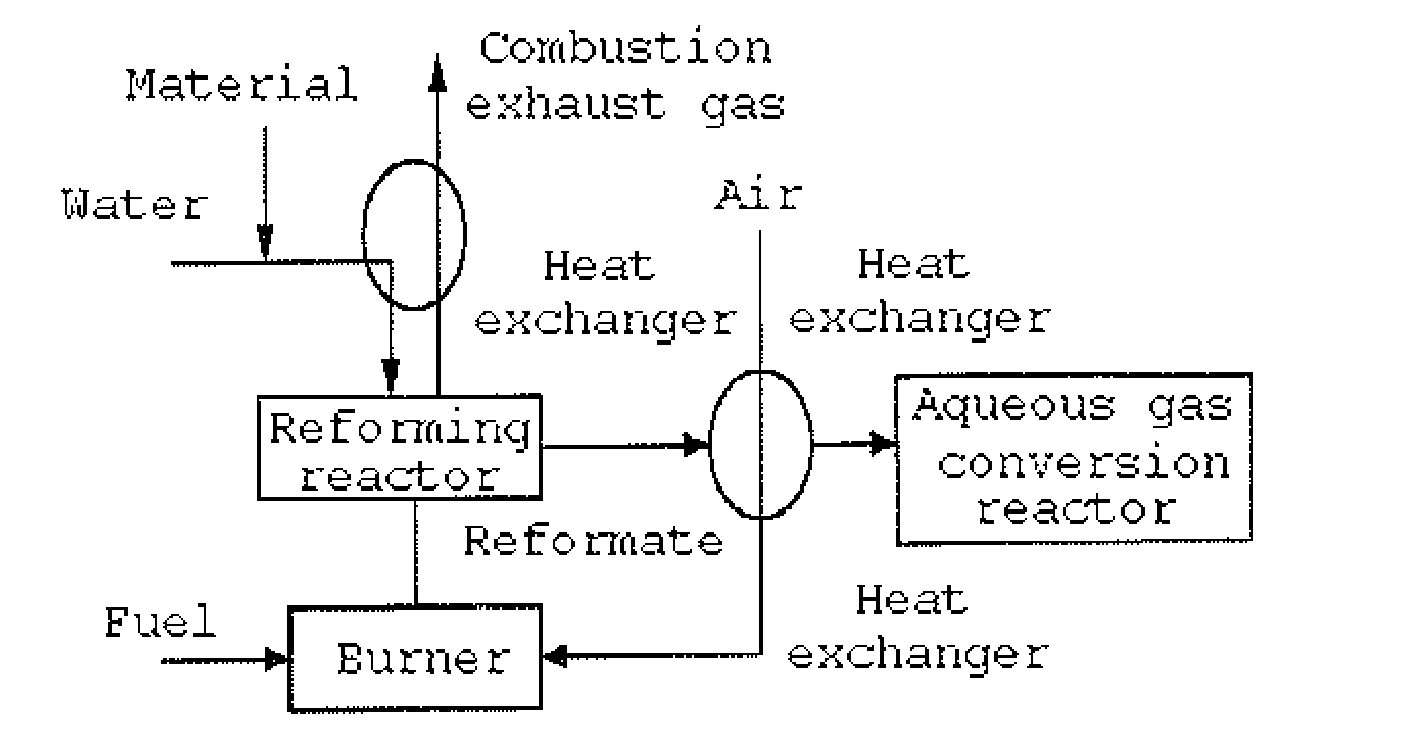
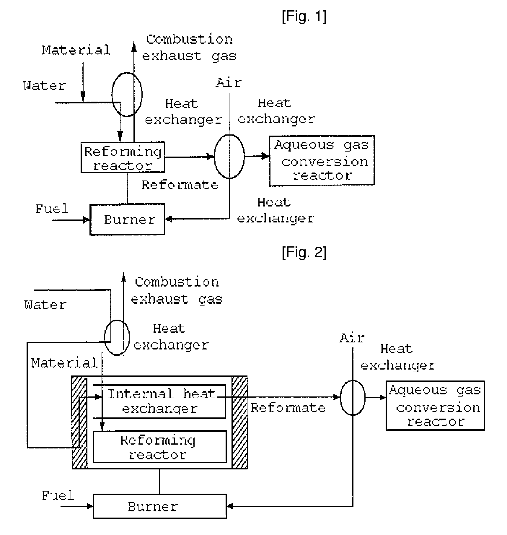
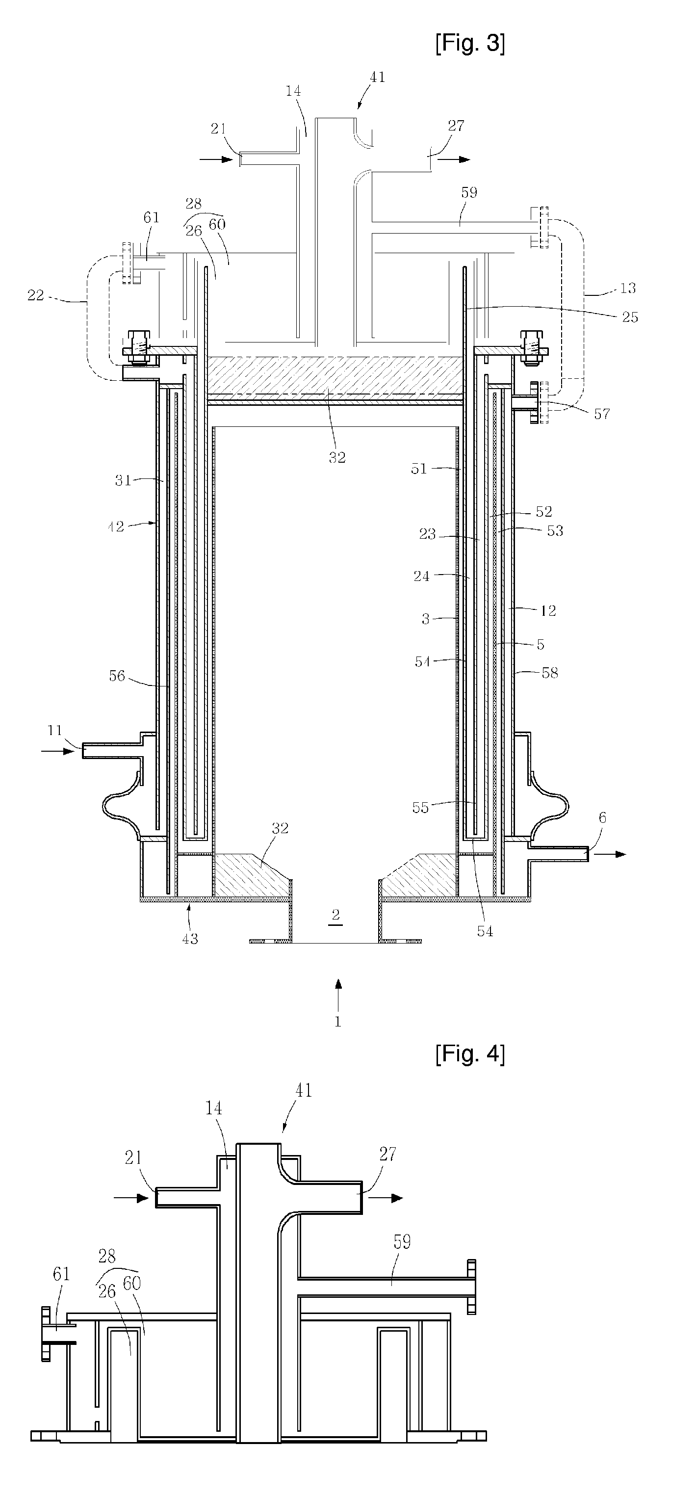
[0021]FIG. 2 schematically shows a steam reformer of the present invention, and FIG. 3 shows the inner structure of the cylindrical steam reformer of the present invention.

[0022]FIGS. 4 to 6 show the inner structure of each of an upper reactor zone, a middle reactor zone, and a lower reactor zone of the steam reformer, according to the present invention.

[0023]The cylindrical steam reformer according to the present invention is schematically shown in FIG. 2. As is apparent from this drawing, the steam reformer of the present invention is characterized by including an internal heat exchange part, a combustion part, a steam generation part, and a reforming part in a single reactor. That is, the cylindrical steam reformer of the present invention is designed to provide the internal heat exchange part in the reactor so as to minimize the size of the external heat exch...


PUM


Abstract

Disclosed herein is a cylindrical steam reformer, including a reforming part, a combustion part, an internal heat exchange part, and a steam generation part, which are integrally manufactured into a single reactor, thus forming an optimal heat exchange network leading to optimal performance of the individual parts. In addition, the steam reformer of this invention is designed in a manner such that an upper reactor zone, a middle reactor zone, and a lower reactor zone are removably connected so as to easily supply a catalyst and increase durability, and therefore such a reformer can be mounted in places which are small and require stability, such as hydrogen stations.

Description

TECHNICAL FIELD[0001]The present invention relates to a cylindrical steam reformer, which can be applied to include fuel cells requiring hydrogen or hydrogen stations for supplying hydrogen to fuel cell vehicles or other similar places, so as to continuously supply hydrogen using natural gas or hydrocarbons.BACKGROUND ART[0002]While problems of limitation of the amount of buried fossil fuel and environmental contamination have occurred, a new era of hydrogen energy using hydrogen, which is a harmless clean fuel as an energy source, is predicted to come. However, there presently exist technical and commercial limitations on producing hydrogen from alternative energy as pure clean energy. Thus, hydrogen is intended to be produced as clean fuel having little contamination using conventional fossil fuels, that is, hydrocarbons including natural gas, as an intermediate step.[0003]Such hydrogen has been already used in various industrial fields, such as ammonia synthesis, methanol synthes...

Claims


Application Information

Patent Timeline
Patent Type & Authority Applications(United States)
IPC IPC(8): B01J8/04
CPCB01J8/0015C01B2203/80B01J8/0257B01J8/0278B01J8/0285B01J2208/00309B01J2208/00495B01J2208/00504B01J2208/00522B01J2208/0053B01J2208/00752B01J2208/00769B01J2208/00884B01J2219/00265C01B3/384C01B3/48C01B2203/0233C01B2203/0283C01B2203/043C01B2203/066C01B2203/0811C01B2203/0822C01B2203/0827C01B2203/1294C01B2203/1604B01J8/008Y02P20/10B25J5/007B25J19/023F16L55/30F16L2101/30
Inventor YOON, YOUNG SEEKKIM, JIN HONGKIM, IL SUCHOI, KEUN SEOB
Owner SK ENERGY CO LTD (KR)
Why Eureka
Try Eureka