
System for the Conversion of Coal to a Gas of Specified Composition

a technology of gasification process and composition, which is applied in the direction of gasification process details, gas contaminants removal, combustion process, etc., can solve the problems of high sulfur coal, unsuitable for coal-fired power generators, and high gas production during coal gasification

Inactive Publication Date: 2008-09-18
PLASCO ENERGY GROUP INC
View PDF45 Cites 164 Cited by
  • Summary
  • Abstract
  • Description
  • Claims
  • Application Information

AI Technical Summary

Benefits of technology

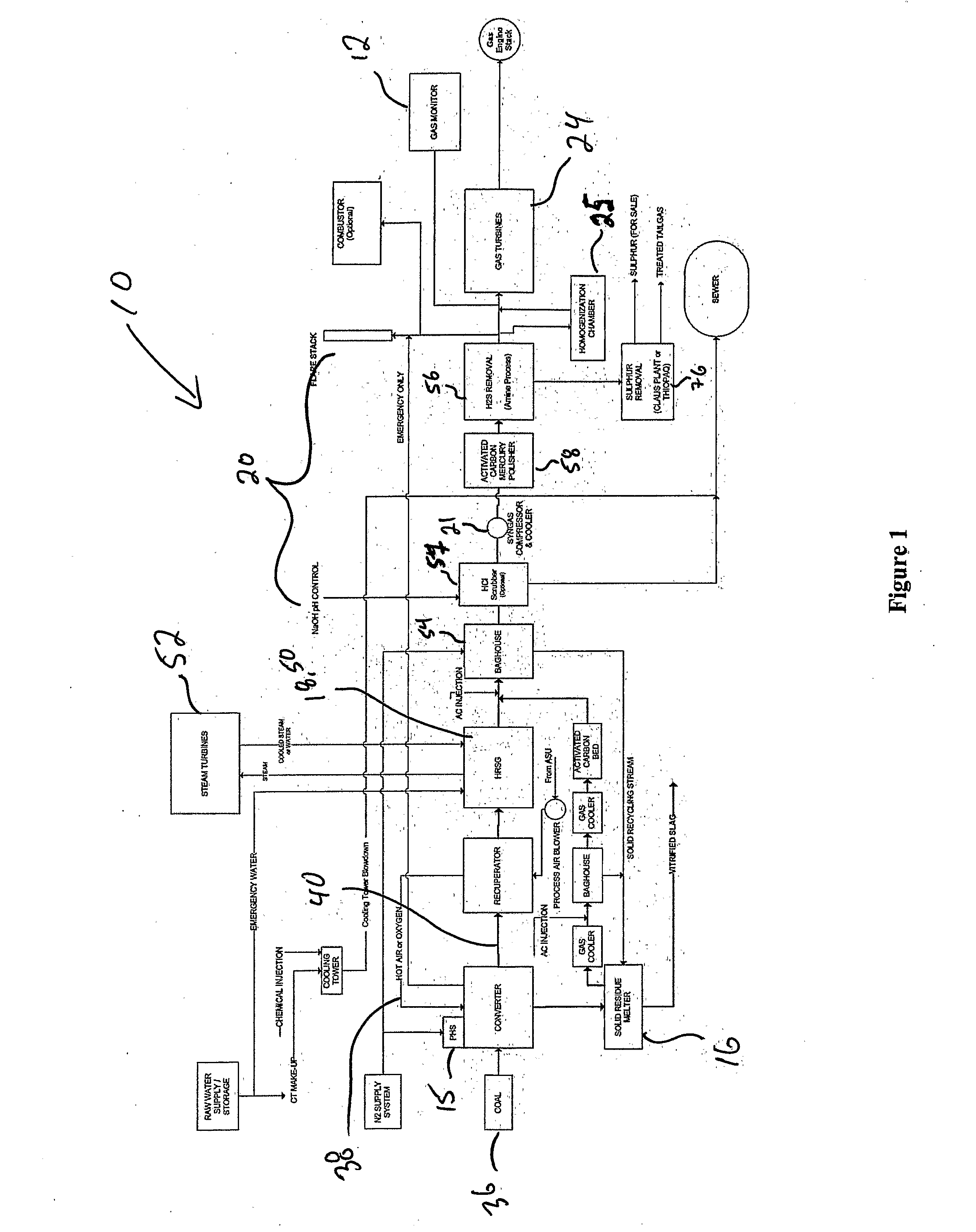
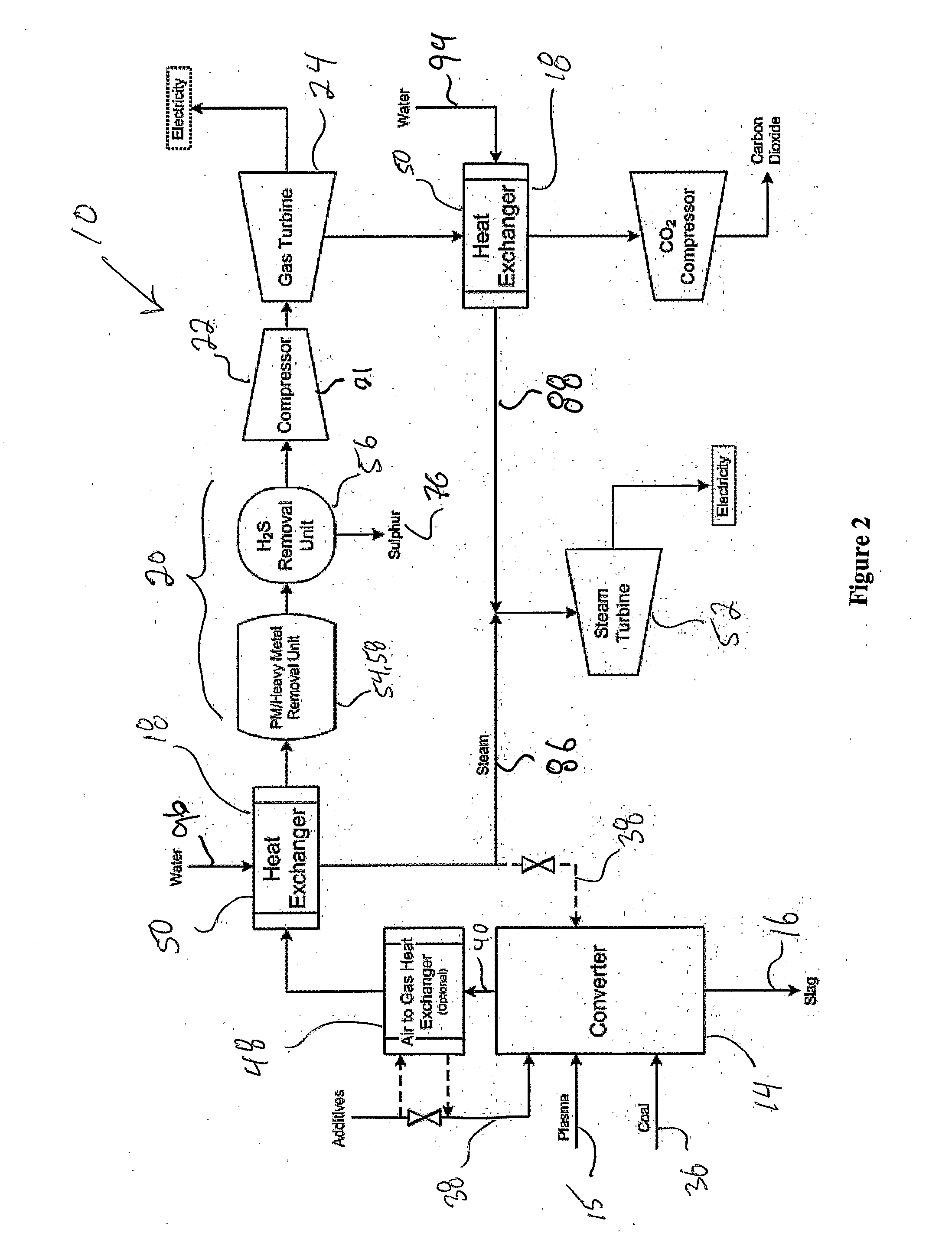
"The present invention provides a system for converting coal to a gas with a specific composition. The system includes a gasification reaction vessel with plasma heat sources and a coal input means for adjustable coal feed rate. The system also has a process additive input means for adjustable process additive feed rate and an outlet for the output gas. The system includes a solid residue handling subsystem and a gas quality conditioning subsystem. An integrated control system monitors system parameters and sends signals to regulators to effect change in the system. The gasification system may also have a heat recovery subsystem and a product gas regulating subsystem."

Problems solved by technology

This includes low grade, high sulfur coal, which is not suitable for use in coal-fired power generators due to the production of emissions having high sulfur content.
The gas produced during the gasification of coal is usually very hot and dirty, and requires further treatment to convert it into a useable product.
These machines are designed to function within a very strict range of characteristics and are often very sensitive to changes in gas characteristics.
In addition to affecting the efficiency of engine operation, a deviation in the gas characteristics may even have a negative effect on engine operation.
For example, changes in the gas characteristics can affect the corrosion protection properties of the lubricating oil in an engine, as well it can affect emissions, efficiency, knock and combustion stability.

Method used


Image

  • System for the Conversion of Coal to a Gas of Specified Composition
  • System for the Conversion of Coal to a Gas of Specified Composition
  • System for the Conversion of Coal to a Gas of Specified Composition

Examples


example

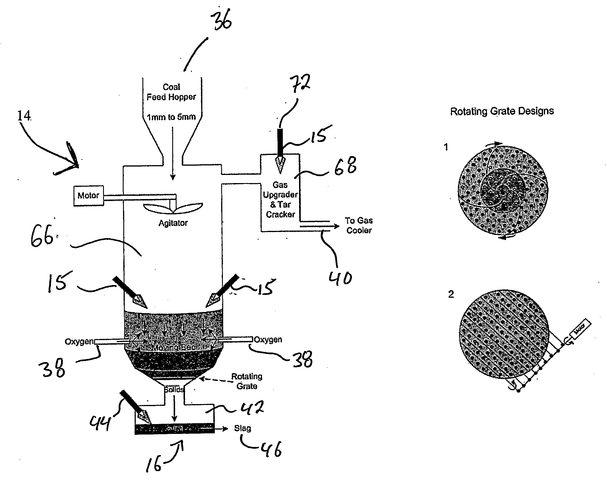
[0278]In general, the system of the present invention is used by feeding the coal along with the heat from a source such as a plasma heat source 15, heated air, or any other heat source as may be appropriate, into a gasification reaction vessel 14 where the feedstock is subjected to sufficient heat to allow the gasification reaction to take place.

[0279]Heating of the coal results in removal of any residual moisture and volatilization of any volatile components, thereby providing a partially oxidized char product. Further heating of the partially oxidized char product completely converts the char to its gaseous constituents, leaving an ash by-product, which can then be further heated and converted to slag.

[0280]Extra oxygen may be injected into the gasification reaction vessel to initiate or to increase the exothermic reactions that produce carbon monoxide, carbon dioxide and carbon particles. The exothermic reactions along with the heat optionally provided by the heated process air ...


PUM

PropertyMeasurementUnit
pressureaaaaaaaaaa
temperatureaaaaaaaaaa

Abstract

The present invention provides a coal gasification system with an integrated control subsystem. The system generally comprises, in various combinations, a gasification reactor vessel (or converter) having one or more processing zones and one or more plasma heat sources, a solid residue handling subsystem, a gas quality conditioning subsystem, as well as an integrated control subsystem for managing the overall energetics of the conversion of coal to energy and maintaining all aspects of the gasification processes at an optimal set point The gasification system may also optionally comprise a heat recovery subsystem and / or a product gas regulating subsystem.

Description

FIELD OF THE INVENTION[0001]This invention relates to the gasification of coal, and in particular to a process and apparatus for the conversion of coal to a gas having a specified composition.BACKGROUND OF THE INVENTION[0002]Coal of varying grades can be used as a primary feedstock for gasification. This includes low grade, high sulfur coal, which is not suitable for use in coal-fired power generators due to the production of emissions having high sulfur content. Waste coal particles and silt that remain after coal has been mined, sorted and washed is also useful for gasification. Coal can typically be gasified with oxygen and steam to produce so-called “synthesis gas” containing carbon monoxide, hydrogen, carbon dioxide, gaseous sulfur compounds and particulates. The gasification step is usually carried out at a temperature in the range of about 650° C. to 1200° C., either at atmospheric pressure or, more commonly, at a high pressure of from about 20 to about 100 atmospheres.[0003]...

Claims


Application Information

Patent Timeline
Patent Type & Authority Applications(United States)
IPC IPC(8): C10J3/60C10J3/20
CPCC10J3/005Y02E20/16C10J3/18C10J3/463C10J3/721C10J3/723C10J2300/06C10J2300/093C10J2300/0959C10J2300/0973C10J2300/1238C10J2300/1618C10J2300/1621C10J2300/1646C10J2300/165C10J2300/1659C10J2300/1671C10J2300/1675C10J2300/1693C10J2300/1869C10J2300/1884F23G2204/201Y02E20/18C10K1/004C10K1/024C10K1/122C10K1/143C10K1/32C10J2300/1687C10J3/16Y02P20/129C10J3/08C10J3/28
Inventor TSANGARIS, ANDREASCAMPBELL, KENNETH C.FEASBY, D. MICHAELLI, KE
Owner PLASCO ENERGY GROUP INC
Learn More