Pillar Structure for Separating or Capturing Target Substance

Inactive Publication Date: 2008-09-18
CANON KK
View PDF18 Cites 19 Cited by
  • Summary
  • Abstract
  • Description
  • Claims
  • Application Information

AI Technical Summary

Benefits of technology

[0021]An object of the present invention is to provide an inexpensive structure having a low flow resistance and capable of stably separating or capturing a specified substance. Another object of the present invention is to provide a separating element, a separating apparatus, a capturing element and a detecting apparatus, utilizing a structure thus obtained. Still another object of the present invention is to provide a separating apparatus and a detecting apparatus, having an excellent light transmittance and applicable to an optical detection.
[0030]The structure of the present invention is applicable for use as a separating element, such as a chromatographic column. In the structure of the present invention, the plural pillars provided in the hollow member having the inner space, being formed by a material containing an inorganic oxide, can show a stable separating or capturing function even for a corrosive substance. Also, since the hollow member having the inner space and the pillars are formed by materials of different compositions, an inexpensive material may be selected for the hollow member having the inner space while maintaining characteristics such as strength of the pillars, whereby the structure can be prepared from various materials.

Problems solved by technology

However, such matrix is considered to contain, because of its structure, many closed spaces which the target substance cannot reach.
Such spaces become wasted and cannot contribute to the reaction, with respect to the volume of the matrix, thus reducing the separating ability as a separating element or the efficiency as a capturing element.
In addition, it is not well reproduced.
Also, in U.S. Patent Application Publication No. 2004 / 0125266 A1, the pillar-like projections are formed with an organic polymer, and a molecule containing a corrosive component captured on the pillar-like projection may reduce the stability of the organic polymer.
In addition, the base plate on which the pillar-like projections are formed is formed from the same material as the organic polymer constituting such pillar-like projections, thus imposing a restriction in forming the pillar-like projections thereon and leading to an increased cost.

Method used


Image

  • Pillar Structure for Separating or Capturing Target Substance
  • Pillar Structure for Separating or Capturing Target Substance
  • Pillar Structure for Separating or Capturing Target Substance

Examples


example 1

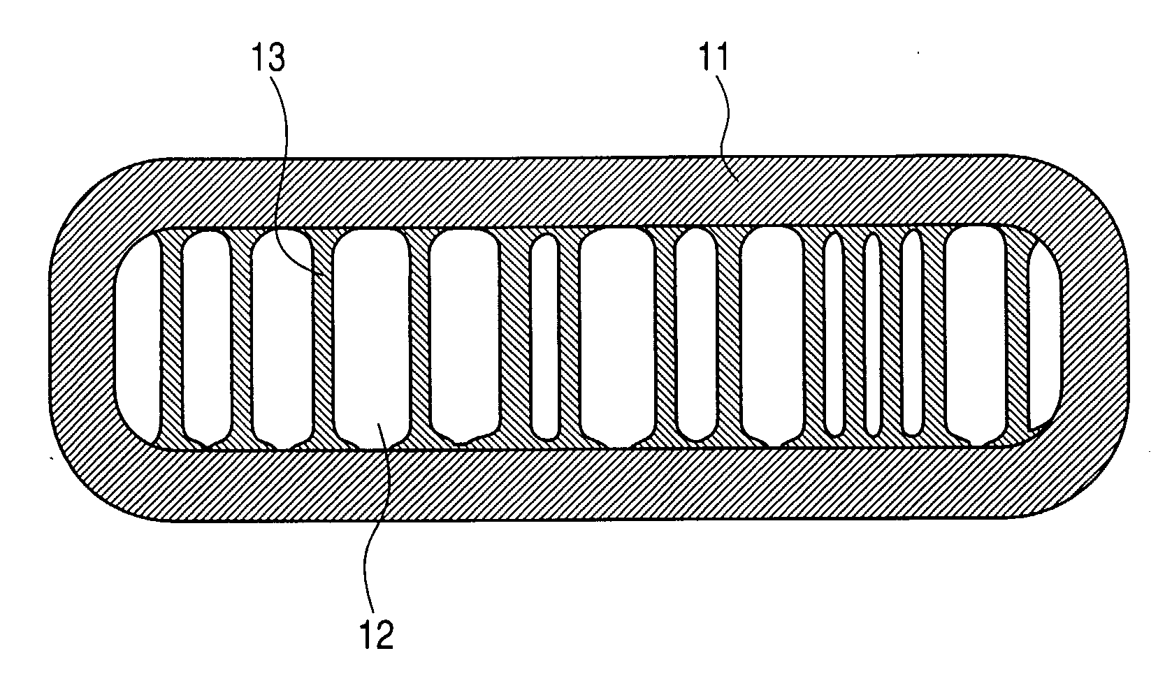
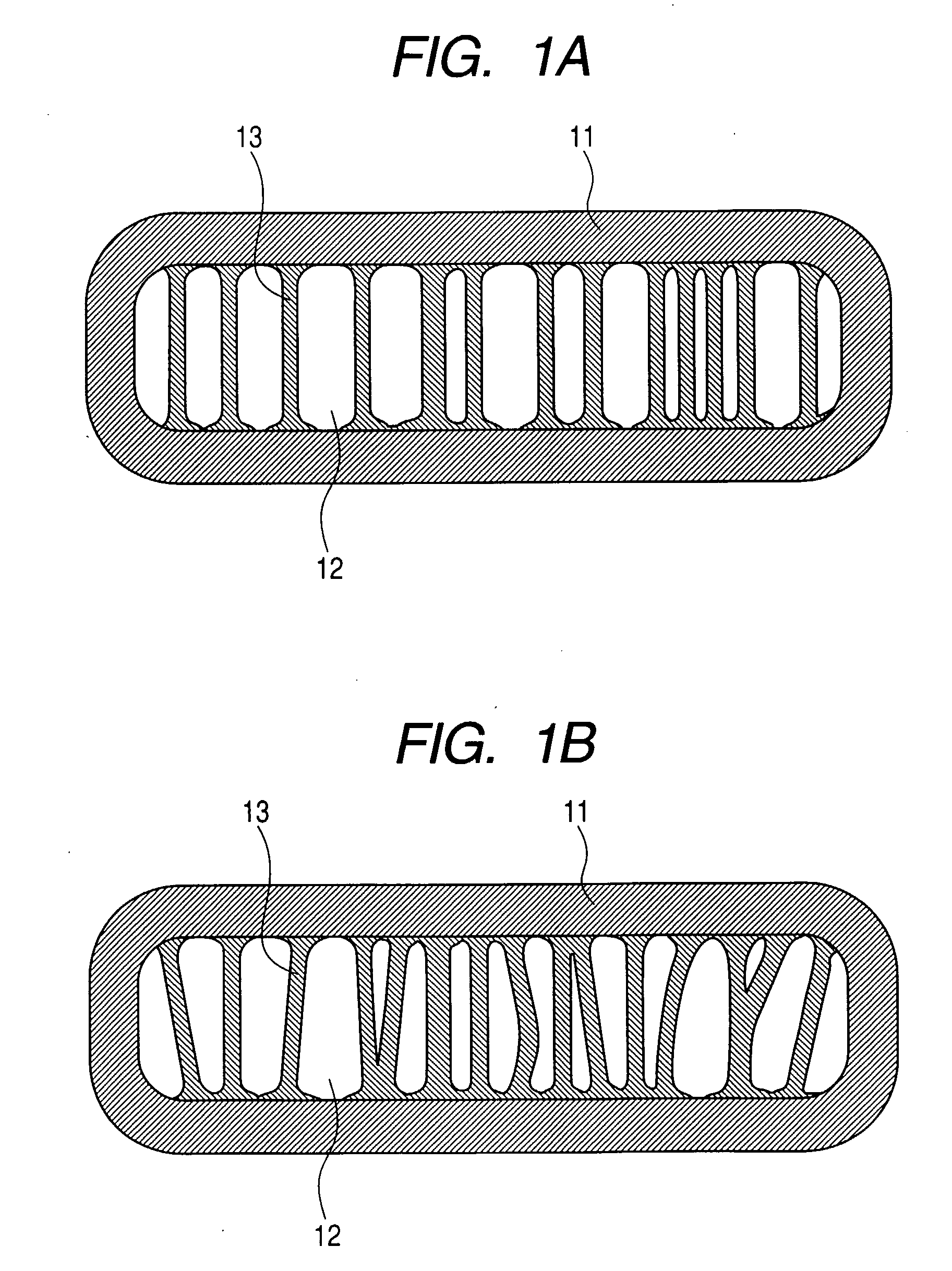
[0106]This example shows a case of employing a glass capillary as the hollow member having an inner space and using a reaction solution constituted of methanol, methyltrimethoxysilane and nitric acid to form plural pillars in the inner space, thereby preparing a structure.

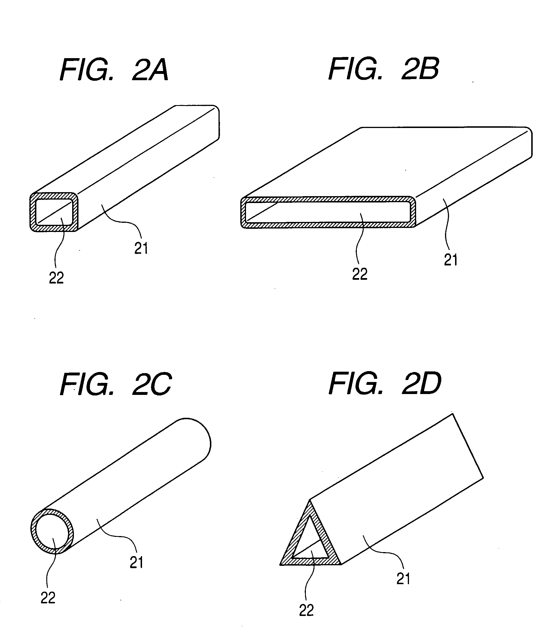
[0107]At first, 1.56 ml of methanol and 1.36 ml of a 1N aqueous solution of nitric acid were mixed and agitated under cooling with ice. Then, 5.0 ml of methyltrimethoxysilane was added and the mixture was agitated for 5 minutes under cooling with ice to obtain a reaction solution. This reaction solution was transferred to a closable resin container, and an end of the glass capillary was contacted with the reaction solution to fill the capillary with the reaction solution. The capillary had an inner space with a height of 100 μm, a width of 1 mm and a length of 50 mm. Then, the capillary, filled with the reaction solution, was immersed in the reaction solution contained in the resin container, which was then closed ...

example 2

[0109]This example shows a case of employing a glass capillary as the hollow member having an inner space and using a reaction solution constituted of methanol, methyltrimethoxysilane and nitric acid to form plural pillars in the inner space, thereby preparing a structure. In comparison with Example 1, this example is different particularly in the amount of methanol. The structure of the formed pillars can be changed by changing the amount of solvent as shown in this example.

[0110]At first, methanol and 1.36 ml of a 1N aqueous solution of nitric acid were mixed and agitated under cooling with ice. Three solutions were prepared by changing the amount of methanol as 1.49 ml (solution A), 1.56 ml (solution B) and 1.59 ml (solution C). Then, 5.0 ml of methyltrimethoxysilane was added to each solution and the mixture was agitated for 5 minutes under cooling with ice to obtain reaction solutions A, B and C. Each of these reaction solutions was transferred to a closable resin container, an...

example 3

[0113]This example shows a case of employing a glass capillary as the hollow member having an inner space, and using a reaction solution constituted of methanol, methyltrimethoxysilane, ethyltrimethoxysilane and nitric acid to form plural pillars in the inner space, thereby preparing a structure. The present example employed two inorganic oxide precursors in a mixture. The structure of the formed pillars can be changed by changing the type of the inorganic oxide precursor as shown in this example.

[0114]At first, 0.74 ml of methanol and 1.36 ml of a 1N aqueous solution of nitric acid were mixed and agitated under cooling with ice. Then, 4.75 ml of methyltrimethoxysilane and 0.2791 ml of ethyltrimethoxysilane were added and the mixture was agitated for 5 minutes under cooling with ice to obtain a reaction solution. The reaction solution was transferred to a closable resin container, and an end of the glass capillary was contacted with the reaction solution to fill the capillary with t...


PUM

PropertyMeasurementUnit
Compositionaaaaaaaaaa
Structureaaaaaaaaaa
Separationaaaaaaaaaa

Abstract

A structure having an opening communicating with an inner space is adapted for separating or capturing a substance introduced from the opening into the inner space. The structure comprises a hollow member having the inner space with the opening and plural pillars positioned mutually separately in the inner space. The pillars are formed of a material containing an inorganic oxide and different in composition from the hollow member.

Description

TECHNICAL FIELD[0001]The present invention relates to a structure for separating or capturing a specified substance and a producing method therefor, and a separating element, a capturing element, a separating apparatus, and a detecting apparatus utilizing such structure.BACKGROUND ART[0002]For analyzing a trace amount of a protein or nucleic acid, there have been used apparatuses utilizing electrophoresis or liquid chromatography, as represented by capillary electrophoresis or capillary liquid chromatography. Such apparatuses perform an analysis by filling a glass capillary of an internal diameter of 100 μm or less with a separating matrix. Such analysis utilizing a microspace has yielded an improvement in efficiency. Based on such a situation, it is now being proposed to utilize, instead of a microspace on the order of 100 μm, a microspace on the order of 10 μm or less.[0003]For such a purpose, there is already known a method of utilizing a porous member, for example, a microfilter...

Claims


Application Information

Patent Timeline
IPC IPC(8): B01D61/00B01D71/02B01J19/00G01N21/01G01N21/76G01N21/64
CPCB01J20/28014B01J20/281B01J2220/54B01L3/502753B01L2300/0681G01N2030/524B01L2300/0877B81B1/00B81B2201/0214G01N30/6069B01L2300/0838
Inventor YAMAMICHI, JUNTAOGAWA, MIKINAKANISHI, KAZUKI
Owner CANON KK
Why Eureka
Try Eureka