Laser scanning microscope and method of use

Inactive Publication Date: 2008-09-18
EVIDENT CORP
View PDF7 Cites 12 Cited by
  • Summary
  • Abstract
  • Description
  • Claims
  • Application Information

AI Technical Summary

Benefits of technology

[0010]The objective of the present invention is to provide a laser scanning microscope having a high sensitivity and accuracy in detecting polarization anisotr

Problems solved by technology

Thus, Homo-FRET observations that use a difference in wavelength are not possible.
However, if FRET occurs between the excitation and the emission of fluorescence, the polarization will be disrupted so as to result in

Method used


Image

  • Laser scanning microscope and method of use
  • Laser scanning microscope and method of use
  • Laser scanning microscope and method of use

Examples


embodiment 1

[0049]FIG. 6 is a schematic illustration showing a use of an AOTF 12 in the laser scanning microscope of the present invention. In the present invention, the AOTF 12 (when energized) divides the incident light from the laser 9 into a zero-order diffracted light beam (not illustrated, but that travels along same optical path as a transmitted beam 26 that emerges from the AOTF 12 when the AOTF 12 is not energized) and a first-order diffracted light beam 27. These beams are then directed to fiber coupling mechanisms 13, 13 that connect to fiber optic transmission media 7, 7 respectively. In other words, both the zero-order diffracted light beam and the transmitted beam 26 are used in the present invention, whereas they are not used in prior art laser scanning microscopes.

[0050]The transmitted light beam 26 (that emerges from the AOTF 12 when it is not energized) and the first-order diffracted light beam 27 (produced when the AOTF is energized) are linearly polarized with vibration plan...

embodiment 2

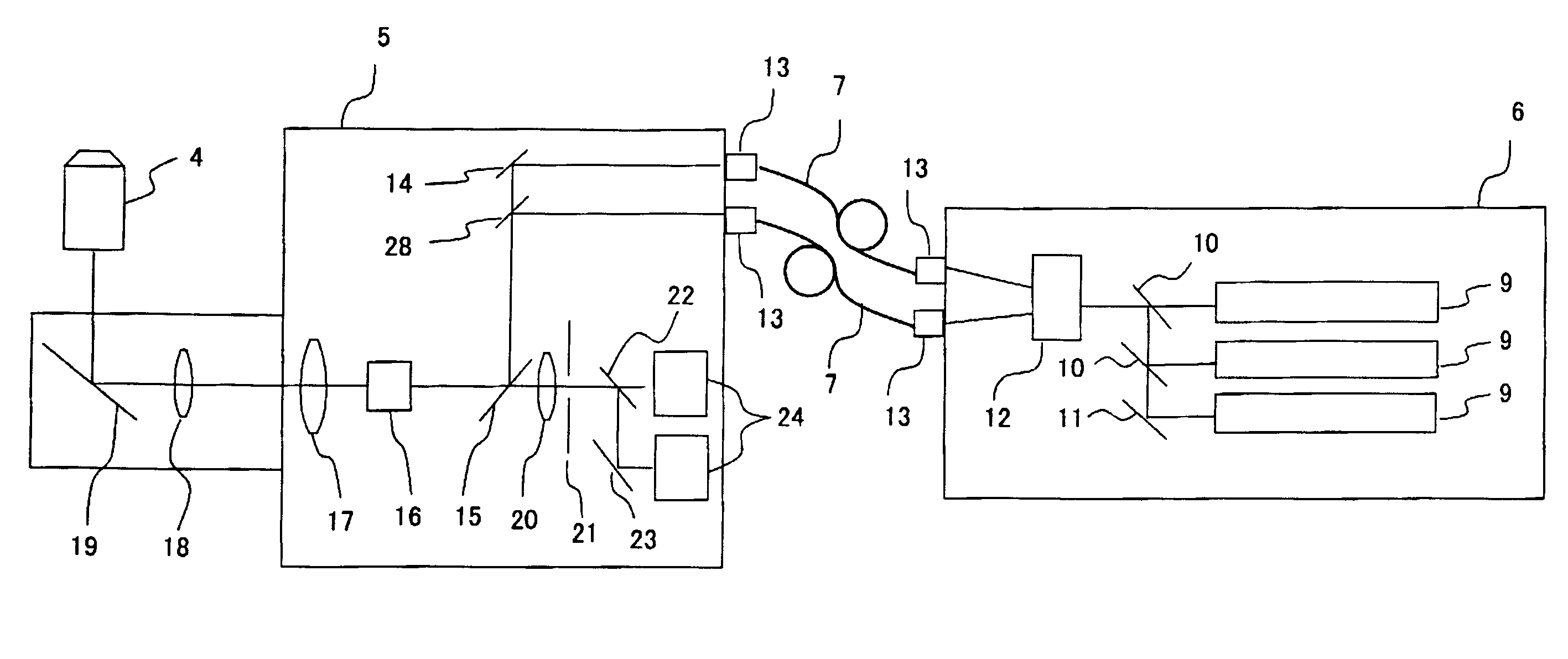
[0053]FIG. 8 is a schematic illustration for explaining another structure relating to the AOTF 12 in the laser scanning microscope of the present invention. In Embodiment 2, the incident light from the laser 9 is split into a transmitted light beam 26 when the AOTF is not energized and a first-order diffracted light beam 27 when the AOTF is energized, which are merged before entering the fiber coupling mechanism 13. In the embodiment shown, a combination of a half mirror 28 and a mirror 29 is used to merge these two light beams so that they travel on a common light path alternately and sequentially.

[0054]FIG. 9 is a schematic diagram showing the internal structure of a laser scanning microscope in which the structure relating to the AOTF 12 shown in FIG. 8 is incorporated. As seen from the comparison between FIGS. 9 and 4, the only difference between the two structures resides in the internal structure of the laser unit 6.

[0055]In the structure of this embodiment, lights from the la...

embodiment 3

[0056]FIG. 10 is a schematic illustration for explaining another use of an AOTF 12 in the laser scanning microscope of the present invention. An AOTF is used to control the amount of light in the prior art laser scanning microscope. In this embodiment, it is used to control the intensity of the light and to switch the directions of the vibration planes of linearly polarized light beams that sequentially and alternately irradiate a sample.

[0057]Upon entering the AOTF 12, the light from the laser 9 is split into two components that travel within the crystalline structure of the ATOF 12. As described in earlier embodiments, by switching on and off the power to the AOTF 12, the AOTF 12 functions to split light emerging from the AOTF into a transmitted light beam that travels along the path of the zero-order diffracted beam 26 and a first-order diffracted light beam 27. Then, either one of these two light beams is introduced into a fiber coupling mechanism 13. Meanwhile, the other of the...


PUM


Abstract

An improved laser scanning microscope and method of use are disclosed that enable polarization anisotropy measurements to be made with greater sensitivity and accuracy. A controllable optical element is provided in a light path between a laser source and a sample, and is controlled so that the sample is alternately irradiated with light beams that are orthogonally polarized. This enables the signal strength to be higher than with previous laser scanning microscopes. Moreover, because the orthogonally polarized light beams that are alternately incident onto a sample may be switched at a high rate, a reduction may be achieved in the influence of molecular motion within a sample in which high speed biological reactions are observed.

Description

[0001]This application claims the benefit of foreign priority under 35 U.S.C. §119 of JP 2007-062,635 filed Mar. 12, 2007, the disclosure of which is hereby incorporated by reference.BACKGROUND OF THE INVENTION[0002]Recent microscopic observation techniques target not only the form of a sample but also biological reactions in living specimens. Fluorescence observation using homo-fluorescence resonance energy transfer (hereinafter termed ‘Homo-FRET’) is known as one such observation technique.[0003]Fluorescence resonance energy transfer (hereinafter ‘FRET’) is a phenomenon caused by two fluorescent molecules, one of which is termed a ‘donor molecule’ and the other of which is termed an ‘acceptor molecule’. The donor molecule is excited by excitation light and it transfers excitation energy to an adjacent acceptor molecule, whereby the acceptor molecule, which was in the ground state, is excited and emits fluorescence. Some additional requirements, such as the requirement that the don...

Claims


Application Information

Patent Timeline
IPC IPC(8): H01S3/10
CPCG01N21/6445G02B21/0092G02B21/002G01N21/6458
Inventor ISHIHARA, KATASHIHATANO, HITOSHI
Owner EVIDENT CORP
Why Eureka
Try Eureka