Engine Control Device
a control device and engine technology, applied in the direction of electric control, machines/engines, instruments, etc., can solve the problems of low degree of freedom in control, insufficient robustness against deterioration, and inability to start anew, so as to improve the robustness and excellent startability
- Summary
- Abstract
- Description
- Claims
- Application Information
AI Technical Summary
Benefits of technology
Problems solved by technology
Method used
Image
Examples
first embodiment
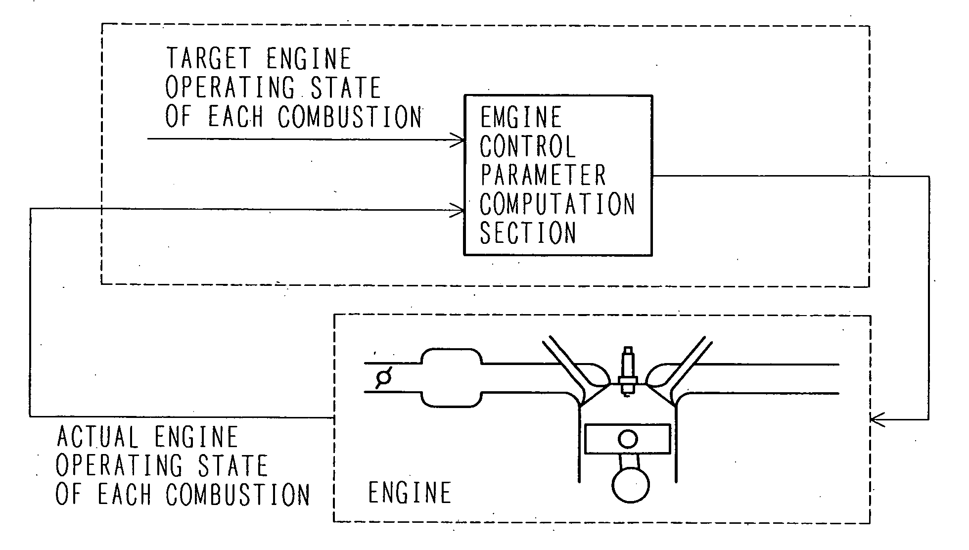
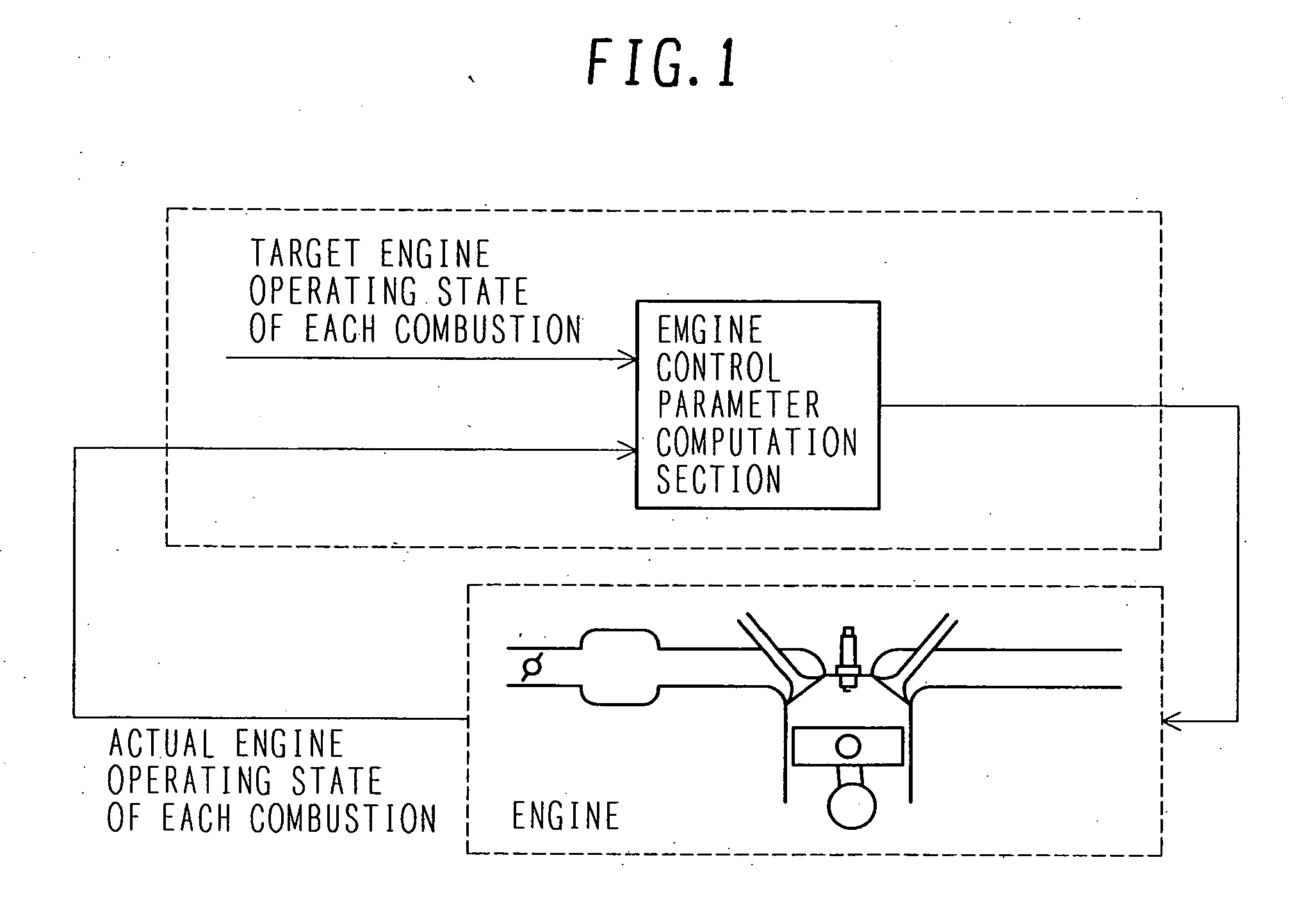
[0067]FIG. 14 shows a system according to a first embodiment of the present invention. In a multiple-cylinder engine 9, outside air passes through an air cleaner 1, travels through an intake manifold 4 and a collector 5, and flows into a cylinder. An intake air amount is adjusted by an electronic throttle 3. An air flow sensor 2 detects the intake air amount. A crank angle sensor 15 outputs a signal at crankshaft rotation angles of 1° and 120°. A water temperature sensor 14 detects the cooling water temperature of the engine. An accelerator opening sensor 13 detects torque demanded by a driver by detecting the depression amount of an accelerator 6. Signals generated from the accelerator opening sensor 13, the air flow sensor 2, a throttle opening sensor 17 mounted on the electronic throttle 3, the crank angle sensor 15, and the water temperature sensor 14 are delivered to a control unit 16. The operating state of the engine is determined from the above sensor outputs to optimally co...
second embodiment
[0097]In the first embodiment, the air amount (fuel amount) of each combustion is used to control a startup combustion (engine speed) profile. In a second embodiment, however, ignition timing is used in addition to the air amount (fuel amount) of each combustion to control a startup combustion (engine speed) profile.
[0098]FIG. 14 shows a system according to the second embodiment of the present invention. The system is not described in detail here because it is identical with the system according to the first embodiment. FIG. 15 shows the inside of a control unit 16 according to the second embodiment. The control unit 16 is not described in detail here because it is identical with the control unit according to the first embodiment.
[0099]FIG. 28 is a block diagram illustrating an overall control system. The control system according to the second embodiment is obtained by adding an ignition timing computation section to the control system according to the first embodiment shown in FIG....
third embodiment
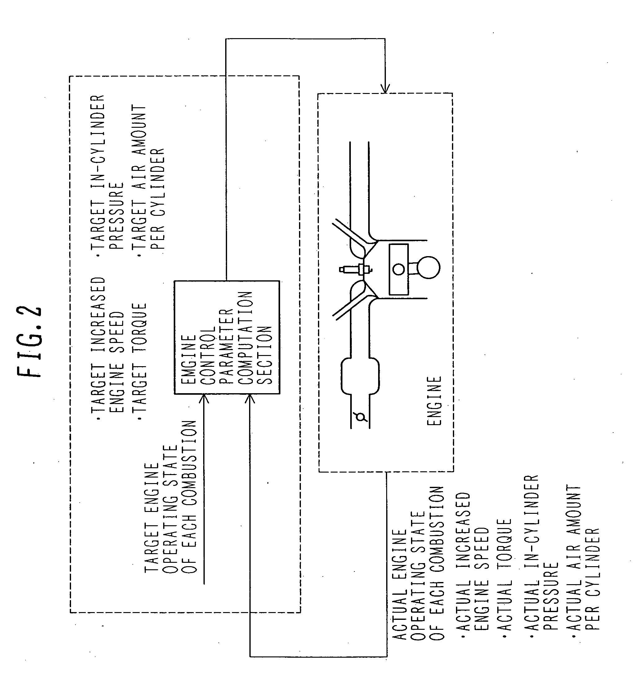
[0121]The first and second embodiments control the increased engine speed of each combustion. However, a third embodiment of the present invention controls the in-cylinder pressure (indicated mean effective pressure) of each combustion.
[0122]FIG. 14 shows a system according to the third embodiment of the present invention. The system is not described in detail here because it is identical with the system according to the first embodiment. FIG. 15 shows the inside of a control unit 16 according to the third embodiment. The control unit 16 is not described in detail here because it is identical with the control unit according to the first embodiment.
[0123]FIG. 31 is a block diagram illustrating an overall control system. The control system includes the following computation sections:
[0124]Startup control permission section (FIG. 17)
[0125]Target indicated mean effective pressure computation section 1 (FIG. 32)
[0126]Actual indicated mean effective pressure computation section (FIG. 33)
[...
PUM
 Abstract
Description
Claims
Application Information
 - R&D
- Intellectual Property
- Life Sciences
- Materials
- Tech Scout
- Unparalleled Data Quality
- Higher Quality Content
- 60% Fewer Hallucinations
Browse by: Latest US Patents, China's latest patents, Technical Efficacy Thesaurus, Application Domain, Technology Topic, Popular Technical Reports.
© 2025 PatSnap. All rights reserved.Legal|Privacy policy|Modern Slavery Act Transparency Statement|Sitemap|About US| Contact US: help@patsnap.com


