Vacuum distillation method and vacuum distillation apparatus

a vacuum distillation and vacuum technology, applied in vacuum distillation separation, chemistry apparatus and processes, separation processes, etc., can solve the problems of sudden drop of pressure, vaporization heat loss from wall surfaces, and inability to greatly anticipate the temperature rise of wall surfaces due to heat transfer, so as to avoid prevent the recurrence of bumping, and reduce the gas pressure in distillation still.

Inactive Publication Date: 2008-09-25
SANYO ELECTRIC CO LTD +1
View PDF4 Cites 4 Cited by
  • Summary
  • Abstract
  • Description
  • Claims
  • Application Information

AI Technical Summary

Benefits of technology

[0008]To solve the aforementioned problems, the present invention provides a vacuum distillation method and a vacuum distillation apparatus which can reliably prevent such an abnormal foaming as to transfer impurities to the heat exchange section, or prevent bumping that causes abnormal foaming.

Problems solved by technology

On this occasion, the reduction of the pressure induces the evaporation of the solvent attached on the inner surfaces of the sidewall and the ceiling wall of the distillation still, leading to vaporization heat loss from those wall surfaces.
Moreover, in the case of vacuum distillation, since the molecular density of the air that contributes to the heat transfer is low, a temperature rise of the wall surfaces due to the heat transfer cannot be greatly expected.
When the solvent starts boiling in the aforementioned situation, the evaporated solvent vapor is cooled to be condensed and liquefied on the inner surfaces of the ceiling wall or the sidewall of the distillation still, causing a sudden drop of the pressure therein.
Consequently, the boiling point of the solvent is abruptly decreased, causing a burst of vigorous boiling, and thus bumping occurs.

Method used


Image

  • Vacuum distillation method and vacuum distillation apparatus
  • Vacuum distillation method and vacuum distillation apparatus
  • Vacuum distillation method and vacuum distillation apparatus

Examples


Embodiment Construction

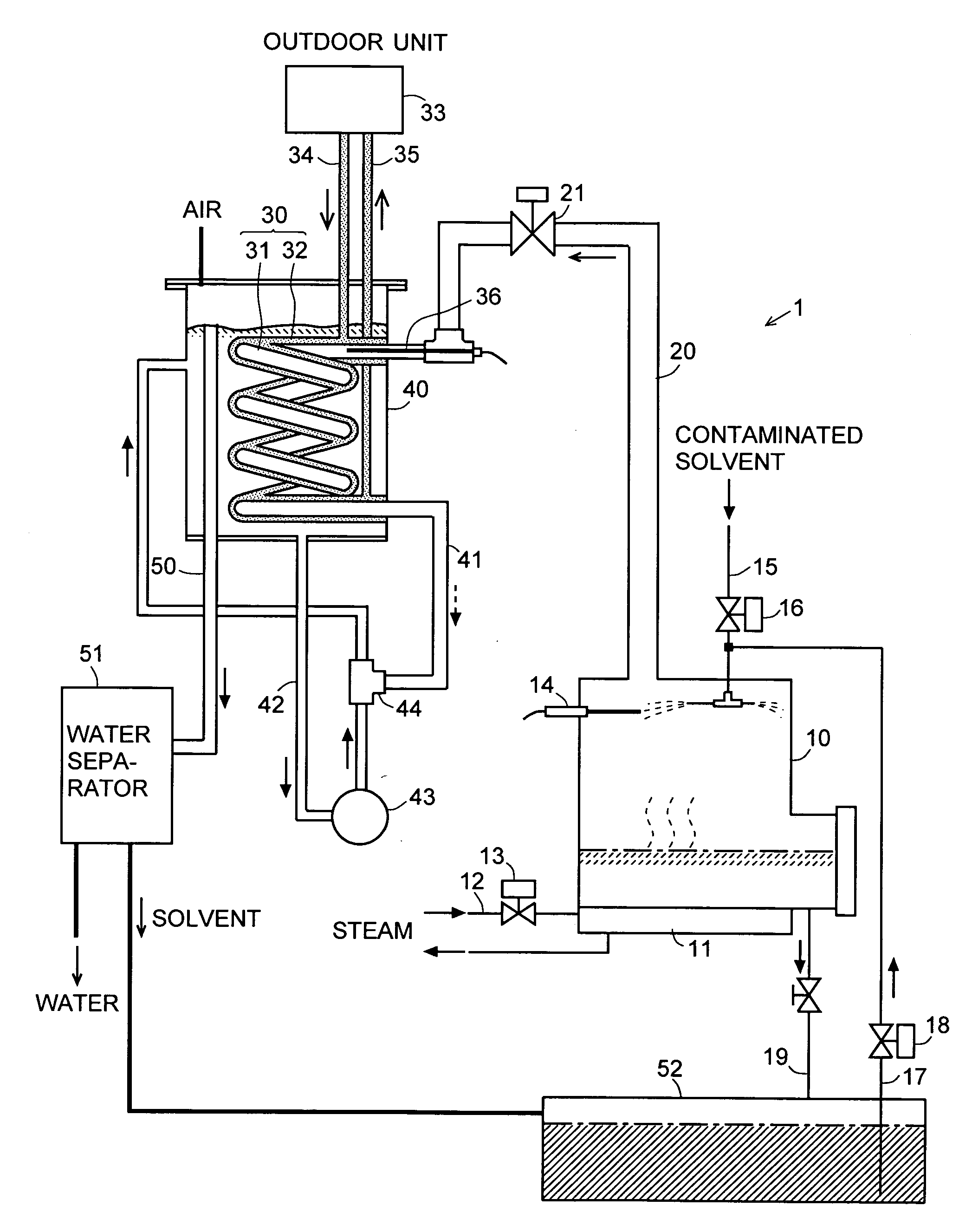
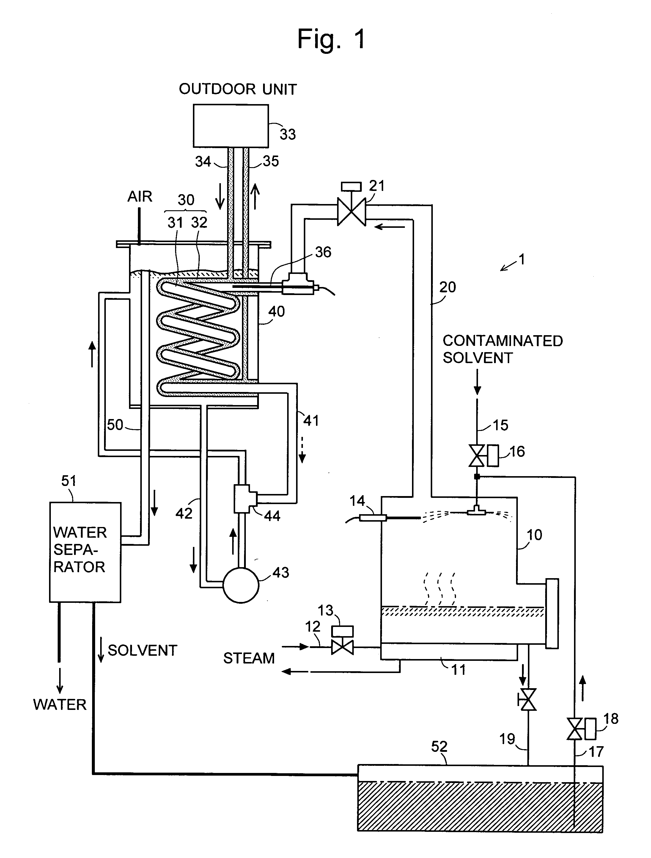
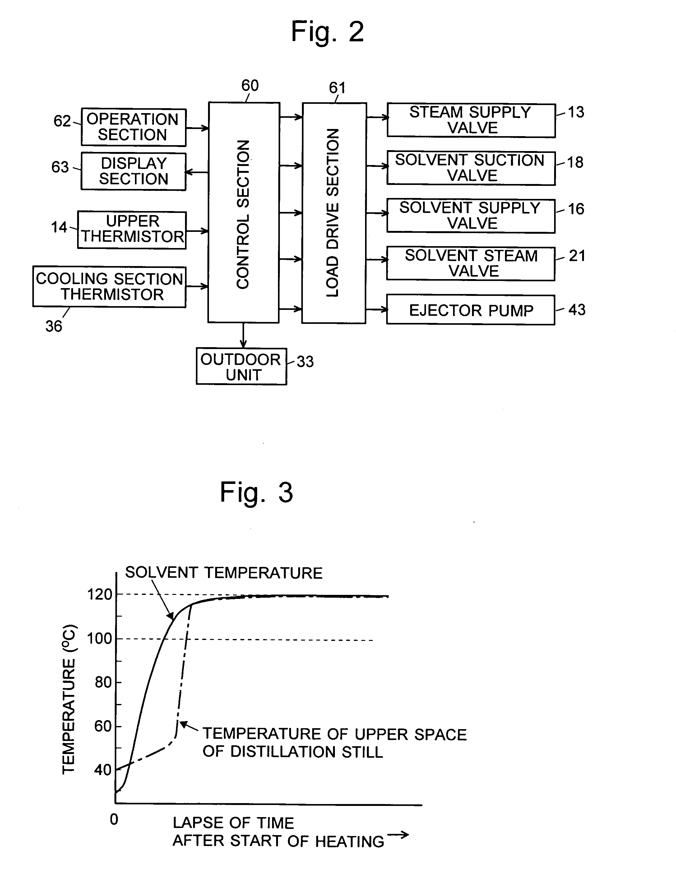
[0038]The following description will discuss one embodiment of the vacuum distillation apparatus of the present invention with reference to FIGS. 1-4. FIG. 1 is a structural diagram showing the vacuum distillation apparatus according to the present embodiment, focusing on the piping route thereof; and FIG. 2 is a structural chart showing a control system of the vacuum distillation apparatus according to the embodiment. In this embodiment, the liquid to be treated of the present invention is a solvent, such as a petroleum solvent or a silicone solvent, used in a dry cleaning machine.

[0039]In a vacuum distillation apparatus 1 according to the present embodiment, a heating chamber 11 which is heated by high-temperature steam supplied via a steam supply pipe 12 while a steam supply valve 13 is open is provided at the bottom portion of a sealable distillation still 10. The distillation still 10 is connected to a solvent supply pipe 15 and a solvent suction pipe 17, and upon the opening o...


PUM


Abstract

An objective of the present invention is to suppress bumping in the distillation still so as to collect a high purity solvent containing no impurities. A solvent vapor valve 21 is disposed in a solvent vapor withdrawal conduit 20 through which solvent vapor is transferred from inside the distillation still 10 to an inner pipe 31 of a double-tube structure 30 which is a heat exchange section. Also, a thermistor 14 is disposed in an upper space in the distillation still 10. After a heating chamber 11 starts heating the solvent, the start of boiling is determined by a sudden rise in temperature detected by the thermistor 14, and shortly thereafter, the solvent vapor valve 21 is closed to fill the distillation still 10 with the solvent vapor. The solvent vapor actively generated by bumping is condensed and liquefied on the cold inner surfaces of a ceiling wall and a sidewall of the distillation still 10, and concurrently, the heat of condensation is provided to the ceiling wall surface and the sidewall surface, thereby accelerating the temperature rise thereof. Bumping stops when the temperatures of the surfaces of the ceiling wall and the sidewall have reached a sufficiently high temperature, and thereafter the valve 21 is opened to transfer the solvent vapor to the double-tube structure 30 functioning as the heat exchange section.

Description

[0001]The present invention relates to a vacuum distillation method and a vacuum distillation apparatus used to purify a liquid to be treated, for example, such as a solvent used in a dry cleaning machine and a solvent utilized to clean various kinds of electronic components.BACKGROUND OF THE INVENTION[0002]In a dry cleaning machine used in cleaners and similar establishments, a vacuum distillation apparatus for purifying a solvent is used to recycle a solvent (silicon oil, petroleum solvent and the like) contaminated by laundry cleaning. For example, a vacuum distillation apparatus disclosed in Patent Document 1 is equipped with a distillation still having a heater section at the bottom; a decompressor including a buffer tank to store a solvent and a pump which vacuums up and pressurizes the solvent in the buffer tank to circulate the solvent through an ejector; and a condenser (heat exchange section) including a cooling portion to cool the solvent in the buffer tank and a cooling ...

Claims


Application Information

Patent Timeline
Patent Type & Authority Applications(United States)
IPC IPC(8): B01D3/10
CPCB01D3/10B01D1/16
Inventor NORO, MASARUNAKAGAWA, KATSUHITOYAMAGUCHI, AKIRA
Owner SANYO ELECTRIC CO LTD
Why Eureka
Try Eureka