
Method and Circuit for Local Clock Generation and Smartcard Including it Thereon

a smartcard and local clock technology, applied in the direction of electric pulse generators, automatic control of pulses, transmission, etc., can solve the problems of power consumption constraints, poor clock generation accuracy, and still remains, so as to improve the accuracy of clock recovery and high precision

Active Publication Date: 2008-09-25
STMICROELECTRONICS SRL +1
View PDF16 Cites 16 Cited by
  • Summary
  • Abstract
  • Description
  • Claims
  • Application Information

AI Technical Summary

Benefits of technology

[0010]The invention adds at least one delay in open loop inside the clock recovery circuit for improving the accuracy of clock recovery. The added delay is shorter than the Step of Time of a known oscillator in such a way that the precision on the jitter is lower than the Step of Time. The added delay enables a higher precision on the granularity of the clock recovery circuit. Different improvements are also made for calibrating the added delay as a function of the Step of Time. The prior art circuits may also be combined with the invention to obtain a preferred embodiment.

Problems solved by technology

Several problems occur when implementing such an accurate clock generation circuit inside an Integrated Circuit (IC) into a portable device.
The problems are due to the fact that IC technology itself is not very accurate for clock generation.
There are also some constraints regarding the power consumption that has to be as low as possible.
In view of this prior art a problem still remains.
This requirement needs to use a very high frequency in combination with a high number of phases and results in an important power consumption.

Method used


Image

  • Method and Circuit for Local Clock Generation and Smartcard Including it Thereon
  • Method and Circuit for Local Clock Generation and Smartcard Including it Thereon
  • Method and Circuit for Local Clock Generation and Smartcard Including it Thereon

Examples


Embodiment Construction

[0026]The invention will be now described in relation to a smartcard including an USB interface for communicating. The invention can also be applied to other kinds of devices using other communication interfaces, but having equivalent characteristics that necessitate a high frequency and an accurate clock signal. For example, the invention could be used in a Flash Card supporting a plurality of communication protocols, such as USB or the like. Both full-speed and high-speed USB peripheral may benefit from this invention. In the case of high-speed devices, the calibration signal may be microframe broadcasted every ⅛th of ms (125 ps) and have the same frame number eight times during each ms.

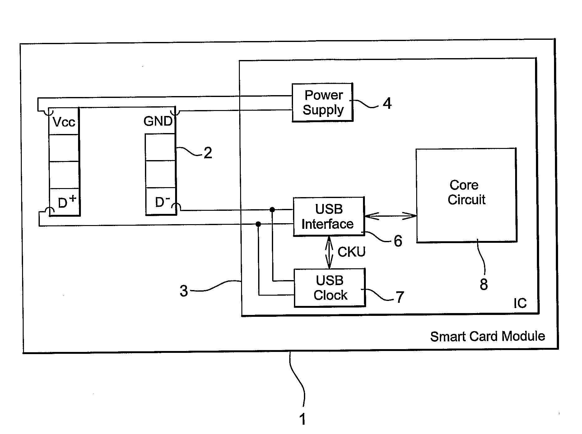
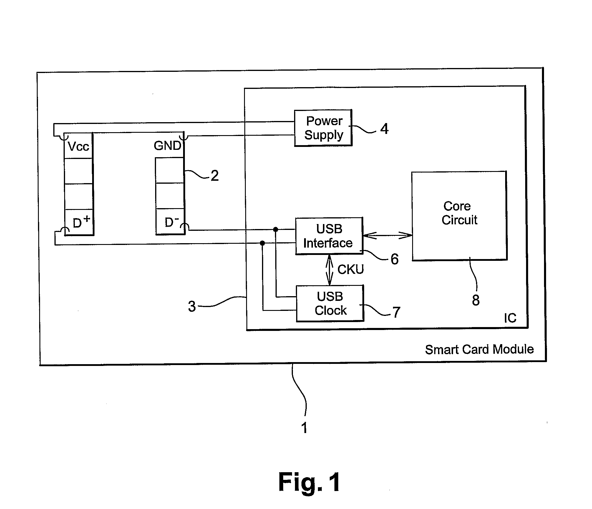
[0027]FIG. 1 shows a smart card module 1 to be inserted in a plastic body card of a smart card like a credit card or a SIM card. FIG. 1 corresponds to both the prior art and to the invention. The smart card module 1 comprises an ISO connector 2 linked to an Integrated Circuit (IC) 3. The ISO connec...


PUM


Abstract

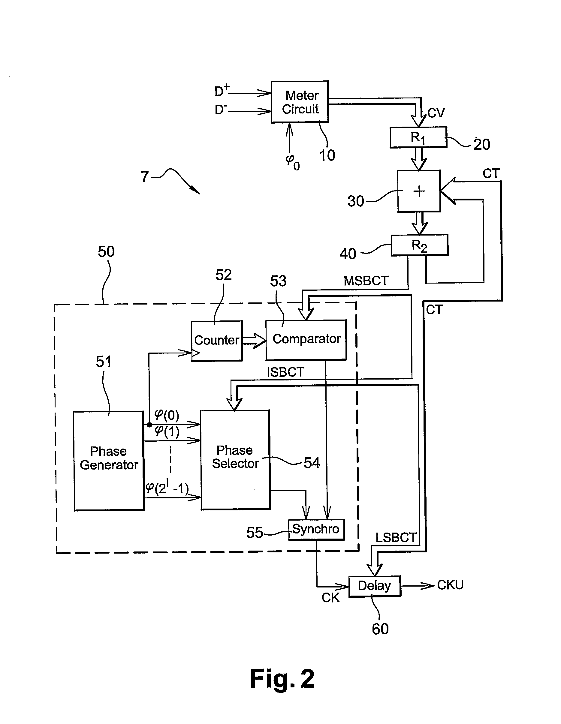
One delay circuit is inserted in open loop inside a clock recovery circuit for improving the accuracy of clock recovery. One oscillator signal φ(0) to φ(2i-1) is provided with a basic Step of Time. A rational number of Step of Time corresponding to a bit-duration is measured inside a received flow of bits. The oscillator signal φ(0) to j(2i-1) is transformed into a clock signal CK having active edges of said clock signal in phase with at least one oscillator signal φ(0) to φ(2i-1), two consecutive active edges being separated by a time duration proportional to the integer part of the number of Step of Time. A time delay is computed proportional to the fractional part of the number of Step of Time. The next active edge of the clock signal CK is delayed of said computed delay.

Description

BACKGROUND OF THE INVENTION[0001]1. Field of the Invention[0002]The invention relates to local clock generation. More particularly, the invention relates to the generation of an accurate clock with a low jitter in a chip, for example the chip of a smartcard supporting USB standard (Universal Serial Bus is defined by a set of specifications published by the USB Implementer Forum). But the invention can be applied to any chip that needs an accurate clock with a low jitter, which clock is recovered from a received stream of data.[0003]2. Description of the Related Art[0004]According to USB standard, any USB device, root hub, hub or peripheral, needs to comprise a clock generation circuit providing an accurate clock signal. The accurate clock signal is required for receiving and sending data. For portable devices like smartcards or Flash cards supporting USB, it is preferable to have an on-chip clock generation circuit.[0005]Several problems occur when implementing such an accurate cloc...

Claims


Application Information

Patent Timeline
IPC IPC(8): H03B21/00G06F1/04G06K19/067
CPCG06F1/04H03K5/135H03K5/133H03K2005/00058H04L7/0338H03K5/156H03L7/197
Inventor LEYDIER, ROBERTPOMET, ALAINDUVAL, BENJAMIN
Owner STMICROELECTRONICS SRL
Learn More