Vibration-isolating fixing mechanism for fan frame

a technology of vibration isolation and fixing mechanism, which is applied in the direction of electrical apparatus casing/cabinet/drawer, other chemical processes, instruments, etc., can solve the problems of most vulnerable storage device, such as a hard disk, and damaged electronic parts inside the computer casing, so as to enhance the fixing function, enhance the fastening and positioning function, and install and uninstall.

Inactive Publication Date: 2008-09-25
INVENTEC CORP
View PDF5 Cites 20 Cited by
  • Summary
  • Abstract
  • Description
  • Claims
  • Application Information

AI Technical Summary

Benefits of technology

[0011]As regards the vibration-isolating fixing mechanism for the fan frame of the present invention, the coupling portions symmetrically flank the fan frame and are each axially formed with a slot for insertion by each of the coupling elements and for fastening to the coupling elements by deformation. Each of the coupling elements is made of rubber, plastics, wood, or metal. In a preferred embodiment, the coupling elements are implemented as fixing pins each comprising a pin portion and an abutting portion. The fixing pins are inserted into the coupling portions to achieve an enhanced fixing function.
[0012]As regards the vibration-isolating fixing mechanism for the fan frame of the present invention, each of the pin portions of the coupling elements is outwardly and circumferentially provided with a protruding ring for fastening to the slot of each of coupling portions inserted with the respect coupling element, so as to enhance the fastening and positioning functions of the fan frame and maintain the positioning relationship between the fan frame and the positioning brackets. The abutting portions allow the vibration-isolating fixing mechanism for the fan frame of the present invention to be installed and uninstalled easily. The coupling portions are inserted to the through-holes of the positioning brackets, wherein the through-holes are circumferentially disposed with resilient elements. The abutting portions of the fixing pins are positioned on one side of each resilient element facing away from the fan frame, such that vibration originated from the fan frame is axially damped and reduced because of contact between the abutting portions of the coupling elements and the resilient elements. The coupling portions of the fan frame are penetratingly fastened to the through-holes of the positioning brackets wherein the through-holes are circumferentially disposed with the resilient elements so as to enhance axial vibration isolation and positioning. Each of the resilient elements is resilient plastics, a reed, or a spring. In a preferred embodiment, the resilient elements are plastics resilient elements so as to enhance the positioning of the coupling portions of the fan frame in the through-holes of the positioning brackets and provide vibration isolation for the fan frame, the casing, and related electronic circuits and components.
[0013]The positioning brackets are further provided with second fastening portions for fastening to the casing and securing in position the fan frame to the casing. The second fastening portions are fastened to the first fastening portions protrudingly disposed on the casing, so as to limit the displacement of the first fastening portions and enable ease of installation and uninstallation. The second fastening portions are oval holes. The first fastening portions of the casing are implemented as screws for fastening to the second fastening portions of the positioning brackets. In a preferred embodiment, the second fastening portions of a positioning bracket are implemented as oval holes for fastening to the casing, and each of the second fastening portions of another positioning bracket is defined by the inner rim of the positioning bracket and configured to fasten to a positioning element protrudingly disposed on the casing. Preferably, the through-holes of the positioning brackets are circumferentially disposed with the resilient elements and penetrated by the coupling portions of the fan frame, and the second fastening portions of the positioning brackets are fastened to the first fastening portions protrudingly disposed on the casing, for the sake of the positioning and vibration isolation of the fan frame.
[0014]Accordingly, a vibration-isolating fixing mechanism for a fan frame of the present invention comprises coupling portions flanking and protruding out of the fan frame, positioning brackets each having second fastening portions and through-holes, resilient elements each circumferentially disposed between each of the coupling portions and each of the through-holes, and coupling elements coupled to the coupling portions respectively, positioned on one side of the resilient elements facing away from the fan frame, configured to position the positioning brackets and the fan frame relative to one another, so as to provide vibration isolation and achieve ease of use.

Problems solved by technology

However, the built-in fans are sources of vibration.
Resonance of a computer casing and a fan operating therein readily damages any electronic parts inside the computer casing.
In this regard, a storage device, such as a hard disk, is most vulnerable, because a pick-up head (PUH) that scratches can damage disk sectors and result in data loss.
But the conventional vibration isolation device is inefficient, particularly where more than one built-in fan is installed inside the computer casing.
But the vibration-isolated fan frame has a drawback, that is, a vibration-isolating element has to be screwed to the fan frame, using a screw.
In the event of mass production, the screw prevents space saving and miniaturization, whereas the screwing process is inconvenient and laborious.
Accordingly, an issue calling for urgent solution involves developing a vibration-isolating device dedicated to providing vibration isolation for fans, achieving ease of use, and being operated without any tool.

Method used


Image

  • Vibration-isolating fixing mechanism for fan frame
  • Vibration-isolating fixing mechanism for fan frame
  • Vibration-isolating fixing mechanism for fan frame

Examples


Embodiment Construction

[0020]The following specific embodiments are provided to illustrate the present invention. Persons of skill in the art can readily gain an insight into other advantages and features of the present invention based on the contents disclosed in this specification.

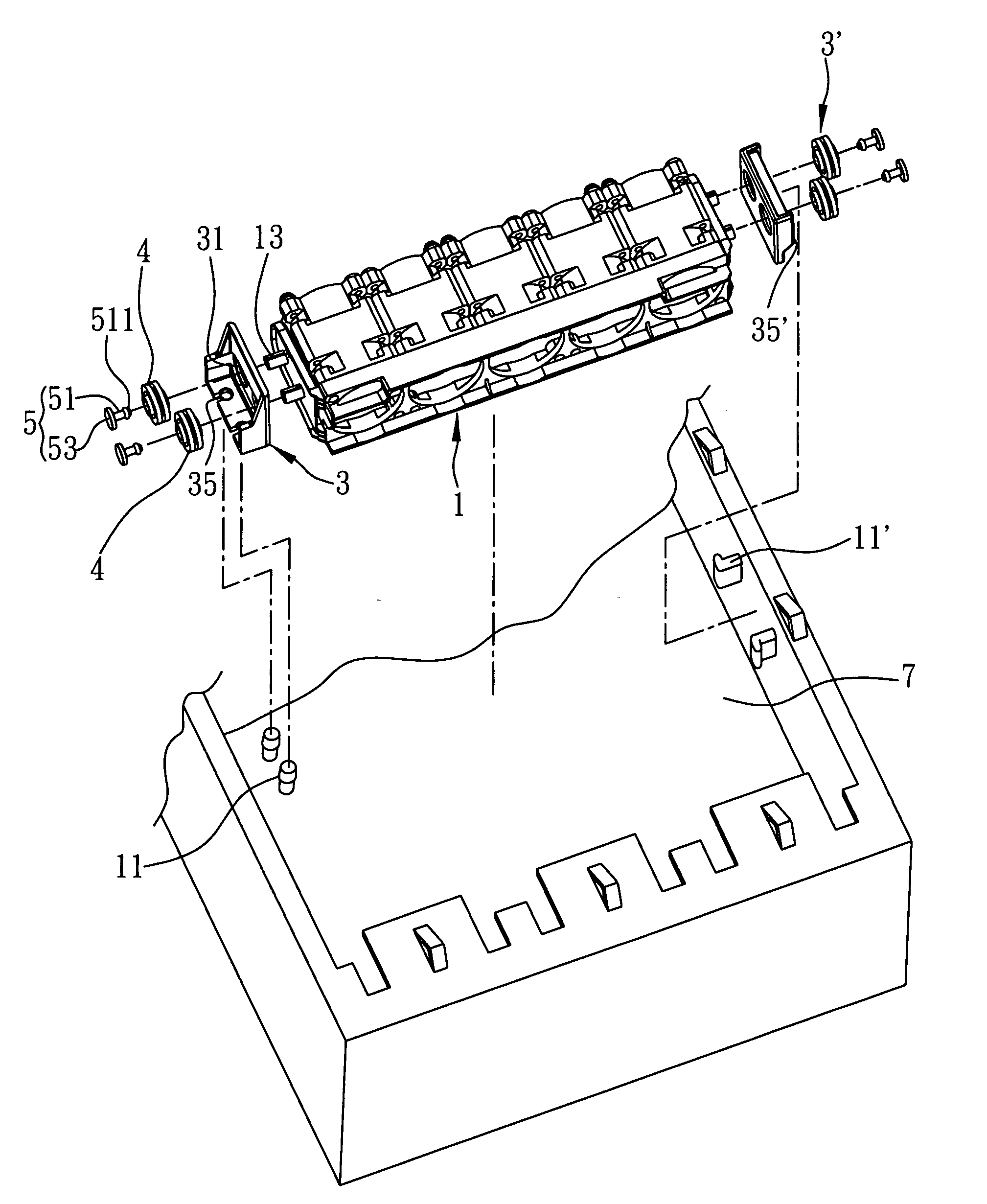
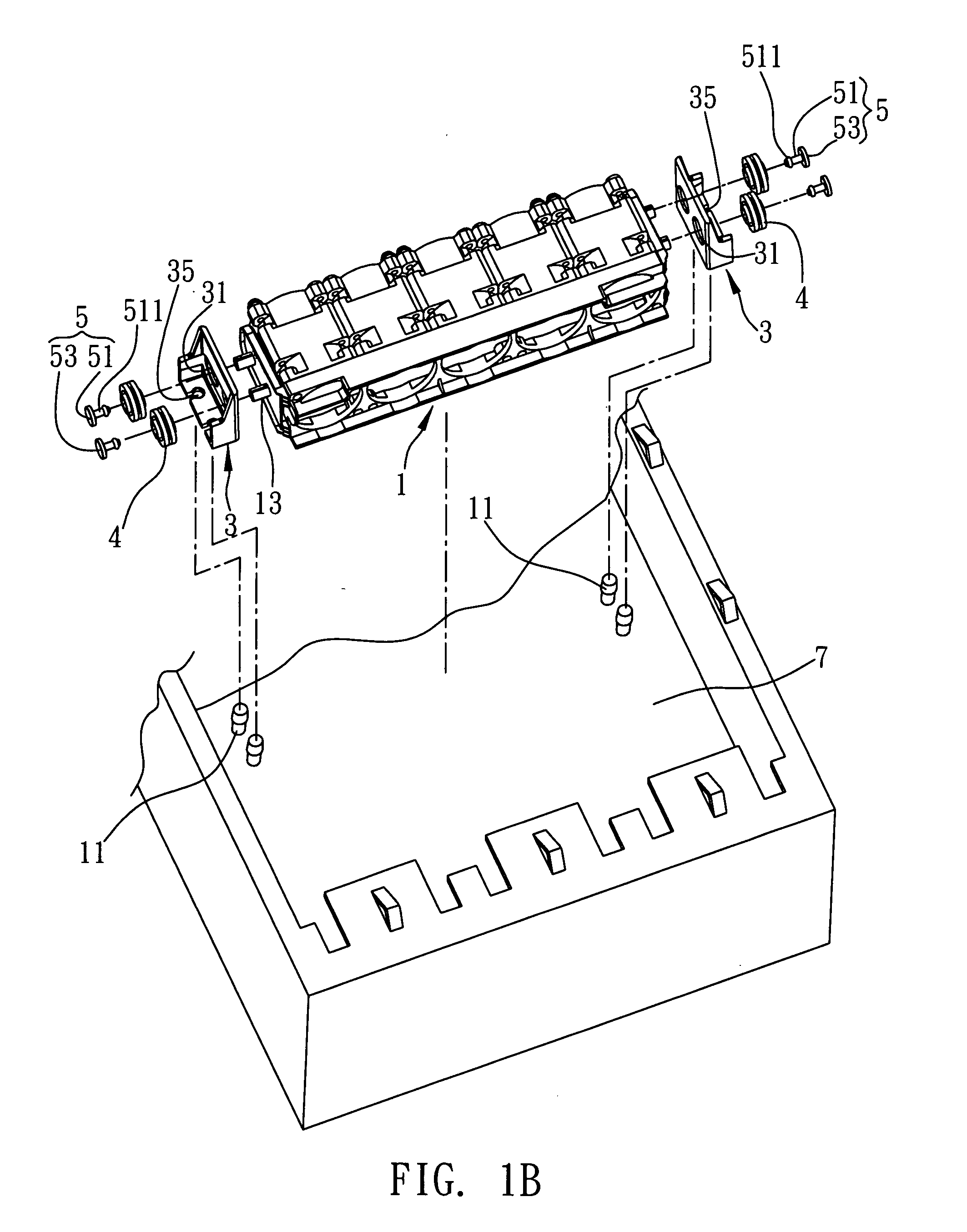
[0021]Referring to FIG. 1A, which is a schematic view showing how to assemble a vibration-isolating fixing mechanism for a fan frame in accordance with the present invention, the vibration-isolating fixing mechanism for a fan frame of the present invention is configured to couple a fan frame to first fastening portions protrudingly disposed on a casing. The vibration-isolating fixing mechanism comprises: coupling portions 13 symmetrically protrudingly disposed on two installation surfaces of the fan frame 1; positioning brackets 3 each having second fastening portions 35 and through-holes 31; resilient elements 4 each circumferentially disposed between each of the coupling portions 13 and each of the through-holes 31; and coup...


PUM


Abstract

A vibration-isolating fixing mechanism for a fan frame. The mechanism, configured to couple the fan frame to first fastening portions of a casing, includes: coupling portions protrudingly disposed on two installation surfaces of the fan frame; positioning brackets each having second fastening portions and through-holes; resilient elements each circumferentially disposed between each coupling portion and each through-hole and extending to two through-hole-corresponding sides of each positioning bracket; and coupling elements coupled to the coupling portions respectively, positioned on one side of each resilient element facing away from the fan frame, and configured to position the positioning brackets and the fan frame relative to one another. Axial vibration isolation is achieved by insertion of the coupling portions into the through-holes circumferentially disposed with the resilient elements and by resilient contact between each resilient element and each coupling element.

Description

BACKGROUND OF THE INVENTION[0001]1. Field of the Invention[0002]The present invention relates to fixing mechanisms, and more particularly, to a vibration-isolating fixing mechanism for a fan frame.[0003]2. Description of the Prior Art[0004]With CPUs becoming faster and peripheral devices becoming more numerous, computers generate heat and scale down more than they have ever before. To meet user needs, computers nowadays are equipped with built-in fans that dissipate heat by forced convection.[0005]However, the built-in fans are sources of vibration. Resonance of a computer casing and a fan operating therein readily damages any electronic parts inside the computer casing. In this regard, a storage device, such as a hard disk, is most vulnerable, because a pick-up head (PUH) that scratches can damage disk sectors and result in data loss.[0006]To minimize vibration, a built-in fan installed inside a computer casing is usually designed to work in the presence of a vibration isolation de...

Claims


Application Information

Patent Timeline
Patent Type & Authority Applications(United States)
IPC IPC(8): G06F1/20
CPCF04D29/601G06F1/20F04D29/666Y10S416/50
Inventor LEE, CHIN-CHENG
Owner INVENTEC CORP
Why Eureka
Try Eureka