Propeller blade

a propeller blade and propeller technology, applied in the field of propeller blades, can solve the problems of increasing drag on the wing, and achieve the effects of reducing the strength of the trailing vortex, reducing the level of the vortex, and reducing drag

Inactive Publication Date: 2008-09-25
SAINT LOUIS UNIVERSITY
View PDF9 Cites 8 Cited by
  • Summary
  • Abstract
  • Description
  • Claims
  • Application Information

AI Technical Summary

Benefits of technology

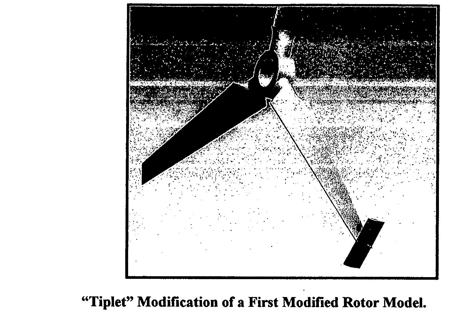
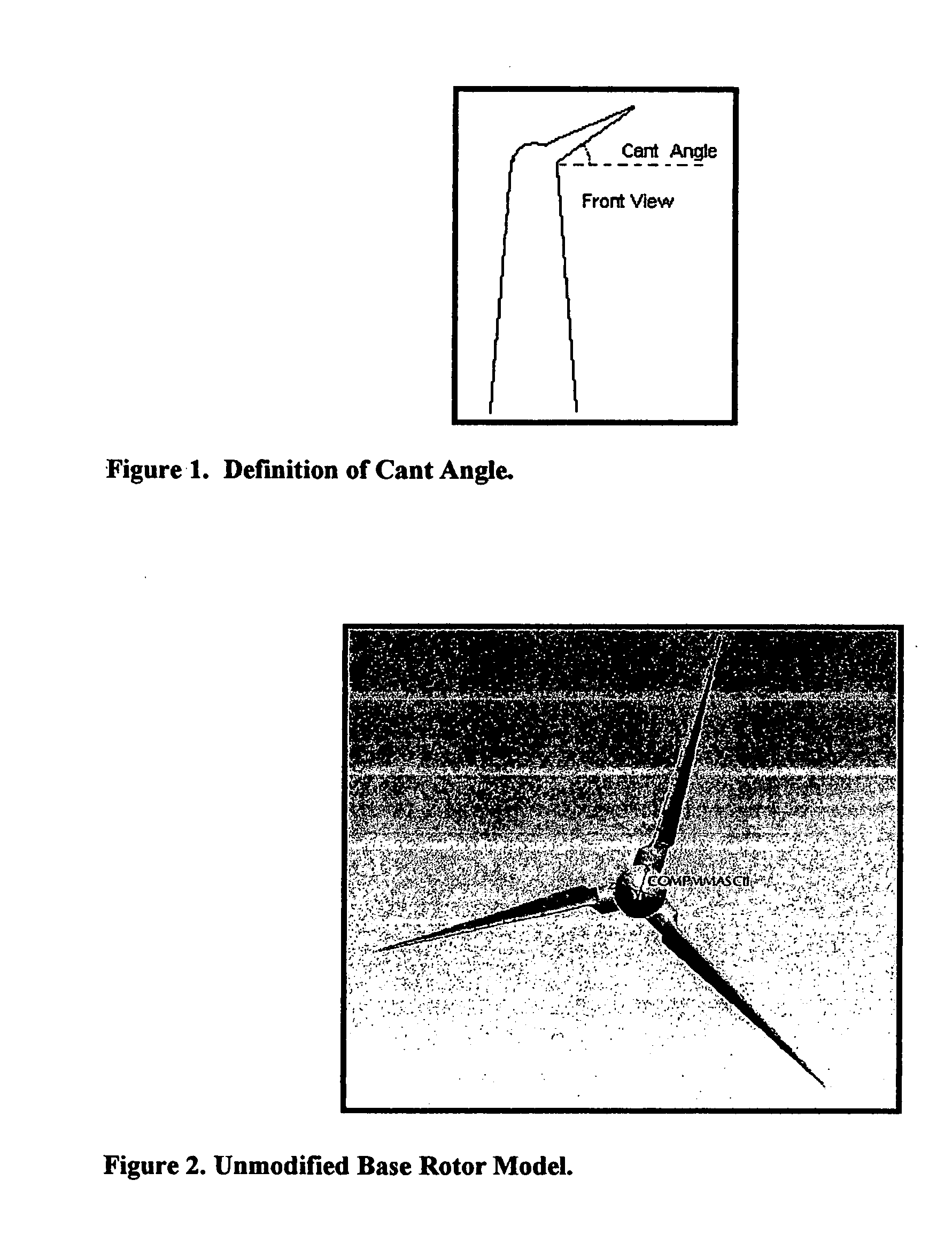
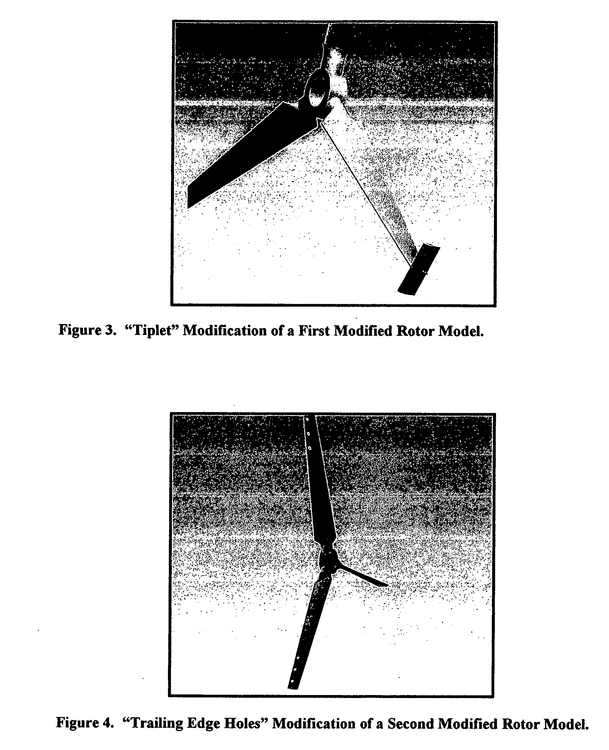
[0009] The strength of the trailing vortex and the amount of drag that it causes on an aircraft is proportional to the weight of the aircraft and the wing size. In a wind turbine propeller blade configuration, the strength of a trailing vortex can be reduced. Different blade tip modifications may be used to reduce the level of the vortex, or to redistribute the high intensity locations, as well as to modify the frequency distributions of trailing vortices. Such blade tip devices should reduce drag, thus increasing thrust or generated power. Blade tip devices that were explored include winglets, trailing edge perforations, radial slots, and tip cylinders.
[0010] Slots and holes in wings have known effects in wing aerodynamics. In the F / A-18, slots in the wing leading edge extension (LEX) were used to mitigate buffet due to the air flow through a slot. This added flow causes the wing vortex flow to be re-energized as it moves aft, thus reducing the flow disturbances from vortex bursting, and hence mitigating buffet effects on the vertical tails.
[0011] The inventor discovered that by modifying propeller blades, especially at or near the tips of the blades, the efficiency of conversion of fluid dynamic energy (e.g., wind and water power) to usable energy, such as electricity, by a wind turbine, significantly improves. Thus, the invention is directed to an improved propeller and improved propeller blade having greater power output and power coefficients; to a method of generating power using an improved propeller blade; and to a method of propulsion using an improved propeller blade.

Problems solved by technology

The downwash velocity caused by this pressure equalization induces increased drag on the wing.

Method used


Image

  • Propeller blade
  • Propeller blade
  • Propeller blade

Examples


Embodiment Construction

[0034] An improved propeller blade is provided. A wind turbine comprising the improved blade produces greater power output and greater power coefficient than a wind turbine comprising unmodified propeller blades. A wind turbine comprising the improved blade also produces greater power output and greater power coefficient than a wind turbine comprising other known blade modifications.

[0035] Figure A shows wing tip vortices as shed in nominal conditions. Since the static pressure on the top of a wing is less than that on the bottom, a flow develops that rotates the air around the tip. For a left-hand wing section, such as depicted in Figure A, the flow rotates in a clockwise direction when viewed from behind. For a right-hand wing section, the flow would rotate in the opposite direction, counter-clockwise. These induced rotational flows are generally called tip vortices.

[0036] The tip vortices tend to remain for a considerable length of time. As the wing moves forward, the vortex re...


PUM


Abstract

An improved propeller blade is presented. The improved blade has a slot near the tip. This improved blade outperforms and is more efficient than other modified and unmodified blade tip configurations.

Description

[0001] This application claims benefit of priority to U.S. Provisional Patent Application No. 60,01,462, which was filed on Jul. 21, 2005.BACKGROUND OF THE INVENTION [0002] 1. Field of the Invention [0003] This invention relates to an improved propeller blade for use in wind turbines, wind mills, aircraft, or watercraft. Specifically, this invention relates to a propeller blade(s) having modifications at or near the tip that allows for more efficient energy transfer and conversion, resulting in greater thrust or propulsive power, or improved power developed for an electrical generator. [0004] 2. Description of the Related Art [0005] The harnessing of wind energy by man for useful purposes, such as in wind mills, spans many millennia. Basic designs for wind mills include the ancient Vertical Axis Wind Mills, VAWM, where the rotation axis is vertical, and the more modern European Wind Mills that were modified to have the rotation axis parallel to the ground, i.e., Horizontal Axis Wind...

Claims


Application Information

Patent Timeline
Patent Type & Authority Applications(United States)
IPC IPC(8): B64C11/16
CPCB63H1/26B64C11/00Y02E10/721F03D1/0633F05B2250/12B64C11/18F05B2240/307Y02E10/72
Inventor FERMAN, MARTY ALLEN
Owner SAINT LOUIS UNIVERSITY
Why Eureka
Try Eureka