Honeycomb filter and exhaust gas purifying apparatus

a technology of exhaust gas purification and honeycomb, which is applied in the direction of catalyst activation/preparation, machines/engines, metal/metal-oxide/metal-hydroxide catalysts, etc., can solve the problems of contamination of the environment and human body, construction machines raising serious problems,

Inactive Publication Date: 2008-10-02
IBIDEN CO LTD
View PDF66 Cites 21 Cited by
  • Summary
  • Abstract
  • Description
  • Claims
  • Application Information

AI Technical Summary

Problems solved by technology

In recent years, particulate matter (hereinafter, also referred to as “PM”) such as soot contained in exhaust gases discharged from internal combustion engines of vehicles such as buses and trucks, and construction machines have raised serious problems as contaminants harmful to the environment and the human body.

Method used


Image

  • Honeycomb filter and exhaust gas purifying apparatus
  • Honeycomb filter and exhaust gas purifying apparatus
  • Honeycomb filter and exhaust gas purifying apparatus

Examples


first embodiment

[0066]Referring to Figures, the following description will discuss a first embodiment which is one of the embodiments of the present invention.

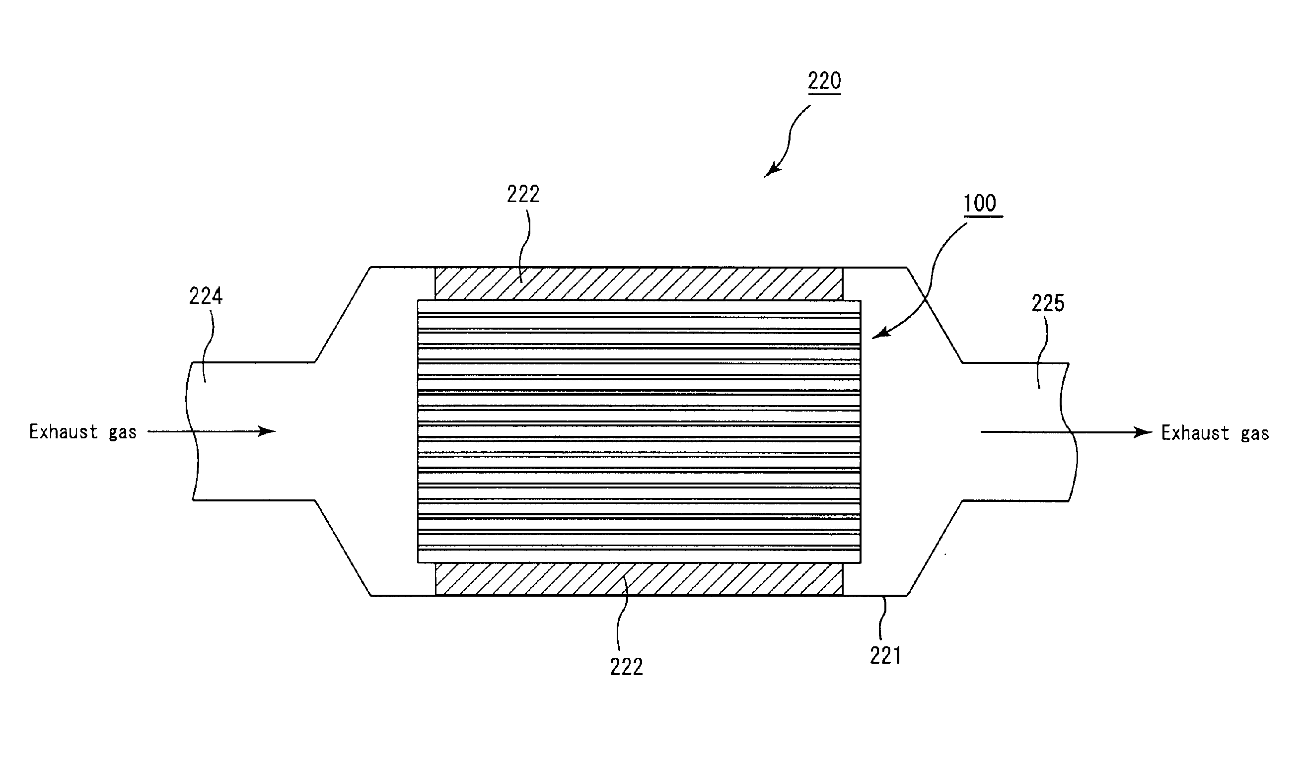
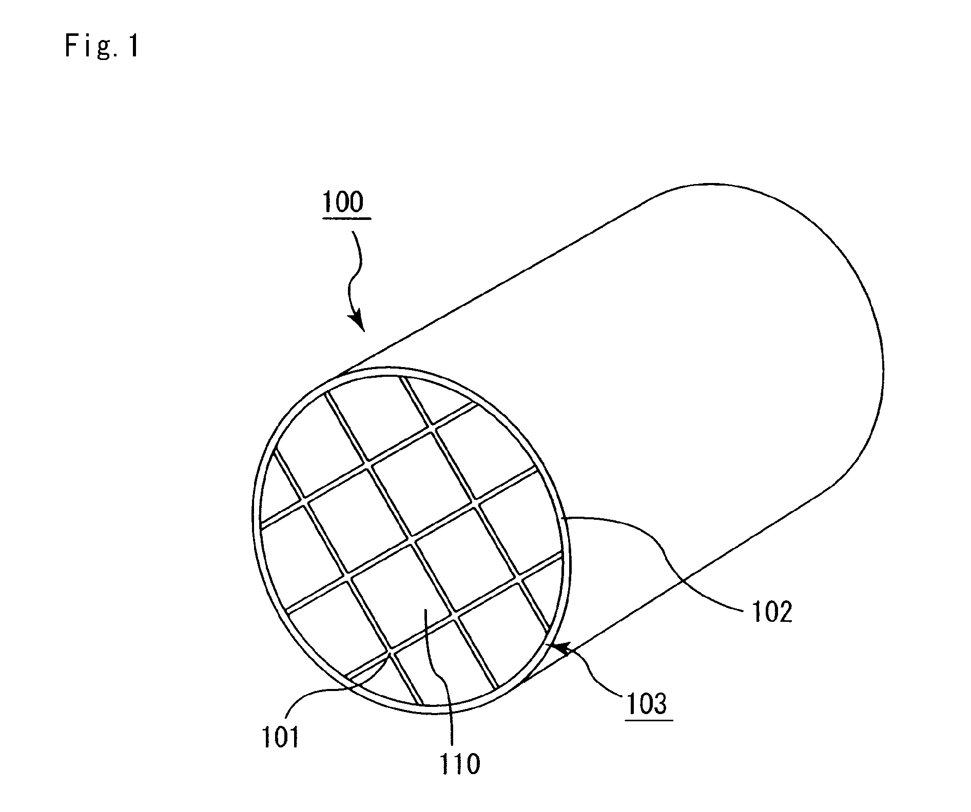
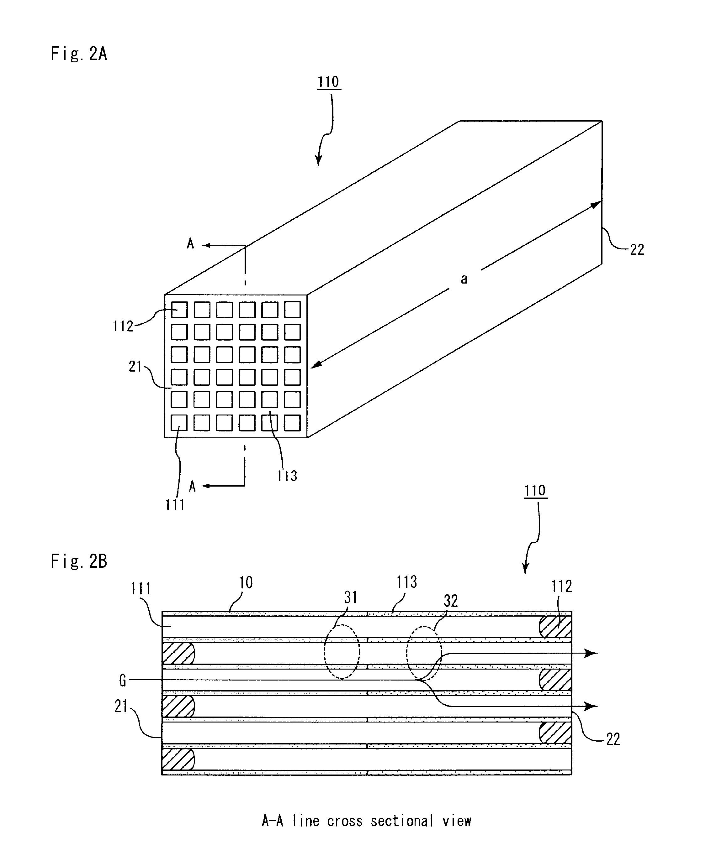
[0067]FIG. 1 is a perspective view schematically showing an example of the honeycomb filter according to the embodiment of the present invention. FIG. 2A is a perspective view schematically showing one example of the honeycomb fired body forming the honeycomb filter according to the embodiment of the present invention, and FIG. 2B is a cross-sectional view taken along the line A-A in the FIG. 2A.

[0068]In a honeycomb filter 100, a plurality of honeycomb fired bodies as shown in FIG. 2A and FIG. 2B are combined with one another by interposing sealing material layers (adhesive layers) 101 in between to configure a ceramic block 103, and a sealing material layer (coat layer) 102 is formed on the outer periphery of the ceramic block 103.

[0069]The honeycomb fired body 110 includes porous silicon carbide as a main component, and is formed by a large...

example 1

Manufacturing of Honeycomb Fired Body

[0125]An amount of 52.8% by weight of coarse powder of silicon carbide having an average particle diameter of 22 μm and an amount of 22.6% by weight of fine powder of silicon carbide having an average particle diameter of 0.5 μm were wet-mixed, and to the resulting mixture were added and kneaded 2.1% by weight of acrylic resin, 4.6% by weight of an organic binder (methylcellulose), 2.8% by weight of a lubricant (UNILUB, made by NOF Corporation), 1.3% by weight of glycerin and 13.8% by weight of water to prepare a mixture, and the mixture was then extrusion-molded to manufacture a raw honeycomb molded body having virtually the same cross sectional shape as the cross sectional shape shown in FIG. 2A, with no cells being sealed.

[0126]Next, the raw honeycomb molded body was dried by using a microwave drying apparatus to obtain a dried body of the honeycomb molded body. Thereafter, a paste having the same composition as that of the raw molded body was...

examples 4 and 5

, Comparative Examples 2 and 3

[0170]By changing the average particle diameter of coarse powder of silicon carbide in the mixture composite, the composition of the raw material and the firing temperature as shown in Table 1, base members 1, 2, 4 and 5 having characteristics as shown in Table 2 were manufactured.

[0171]Each of these base members 1 to 5 had different mode diameters a ranging from 9 to 22 μm.

[0172]On these base members, a catalyst supporting layer was formed by using γ-alumina particles having an average particle diameter of 1.5 μm in the same manner as in Example 2 to manufacture a honeycomb filter as shown in Table 5.

[0173]The respective characteristics of each of these honeycomb filters were measured in the same manner as in Example 1, and the results of the measurements are shown in Table 6 together with the results of Example 2.

TABLE 5Catalyst supporting layer on inlet sideAluminaRange ofFormationAmount ofparticleBaseformationpositionformationdiametermember(%)(mm)(g...


PUM

PropertyMeasurementUnit
lengthaaaaaaaaaa
thermal conductivityaaaaaaaaaa
pore diametersaaaaaaaaaa

Abstract

A honeycomb filter includes a pillar-shaped honeycomb fired body having first and second end faces on a gas inlet and outlet sides, respectively. A catalyst supporting layer is formed in a catalyst-supporting-layer area covering about 25% to about 90% of an overall length of the honeycomb fired body and abutting the first end face on the gas inlet side. Substantially no catalyst supporting layer is formed in a non-catalyst-supporting-layer area covering about 10% of the overall length on the gas outlet side. A thermal conductivity of the non-catalyst-supporting-layer area is higher than that of the catalyst-supporting-layer area, and inequalities, (a−b)≦about 5, and about 10≦a≦about 20 are satisfied where “a” is a mode of pore diameters obtained by measuring pore distribution of the non-catalyst-supporting-layer area and “b” is a mode of pore diameters obtained by measuring pore distribution of the catalyst-supporting-layer area.

Description

CROSS-REFERENCE TO RELATED APPLICATIONS[0001]The present application claims priority under 35 U.S.C. §119 to PCT Application No. PCT / JP2007 / 057302, filed on Mar. 30, 2007, the contents of which are incorporated herein by reference in their entirety.BACKGROUND OF THE INVENTION[0002]1. Field of the Invention[0003]The present invention relates to a honeycomb filter and an exhaust gas purifying apparatus.[0004]2. Discussion of the Background[0005]In recent years, particulate matter (hereinafter, also referred to as “PM”) such as soot contained in exhaust gases discharged from internal combustion engines of vehicles such as buses and trucks, and construction machines have raised serious problems as contaminants harmful to the environment and the human body. For this reason, various honeycomb filters, which use a honeycomb structure made of porous ceramics, have been proposed as filters that capture PM in exhaust gases and purify the exhaust gases.[0006]In a honeycomb filter of this kind,...

Claims


Application Information

Patent Timeline
Patent Type & Authority Applications(United States)
IPC IPC(8): B01D53/86
CPCB01D39/2093B01D46/0001B01D46/0061B01D46/0063B01D46/2429B01D46/2444B01D46/2459B01D46/2466B01D46/4263B01D2046/2437B01D2046/2496B01D2275/30B01D2279/30B01J23/42B01J35/0006B01J35/002B01J35/023B01J37/0242C04B35/565C04B35/806C04B38/0006C04B2111/00793C04B2111/0081F01N3/2828C04B38/0054C04B38/0074C04B35/80B01D46/2498B01D46/24492B01D46/82B01D46/84B01D46/2476B01D46/24494B01D46/2478
Inventor OHNO, KAZUSHIGEOHIRA, AKIHIRO
Owner IBIDEN CO LTD
Why Eureka
Try Eureka