Porous Matrix

a porous matrix and matrix technology, applied in the field of porous matrix, can solve the problems of inadequate diffusion, poor diffusion properties, and failure of treatmen

Active Publication Date: 2008-10-02
REGENTEC
View PDF7 Cites 17 Cited by
  • Summary
  • Abstract
  • Description
  • Claims
  • Application Information

AI Technical Summary

Benefits of technology

[0017]However, the present inventors have found that the matrix may be used as a tissue scaffold without the need to introduce cells. When the tissue scaffold (without cells) is placed in or at a site where it is needed, local endogenous cells can be recruited or encouraged to grow on, in or about the scaffold causing new growth of the existing tissue. This effect is enhanced by the presence of appropriate growth factors being present in the scaffold. Such a situation is particularly useful since there is a much lower chance of rejection, or other immune reaction, of the new tissue than when introducing non-endogenous tissue. Hence, the need for treating a patient with immune suppressants can be reduced and the problems associated therewith can be reduced. Additionally, this technique is useful in patients who are already immune compromised such as cancer patients, the very young, the elderly, pregnant women or people suffering from AIDS or hepatitis B.
[0027]By manipulating the molar ratio of lactic and glycolic acid and the molecular weight of the copolymers, different degradation patterns can be obtained. Poly-L-lactide has a degradation time in vitro of months to years. The long degradation time is due to its high crystallinity which protects the polymer from water penetration. Poly-glycolide has a degradation time of one to several months, whereas poly-D, L-lactide is amorphous and has a degradation time of one to a few months. D, L PLGA has a degradation time in vitro of weeks to months. As the glycolic acid ratio is increased, the rate of degradation increases. Homopolymers of s-caproic acid can remain intact for 2-3 year periods of implantation.
[0032]The present inventors have noted in experiments that osteoprogenitor cells in an in vitro environment under certain conditions will produce cartilage in addition to bone which facilitates endochondral ossification which will allow the tissue engineering of a bone-cartilage interface.
[0037]Ideally, the pore size is of the order of 10-80 μm diameter. This means that the particle size is generally of the order of 50 μm to 1 mm diameter or preferably of 250-500 μm. As can be seen, the overall particle size will be a function of the pore size. That is, the end application of the matrix will dictate the size of the matrix, of the particles and the pore size. For example, where the matrix is not to be loaded with cells, the pore size becomes less critical, provided that diffusion can still occur through the matrix. Additionally, loose packing increases the pore size such that nutrient or other transfer is better, and vice-versa. However, the pore size is not always a function of the cell size since large pores may be seeded with tiny cells. Use of such particles provides the advantage of ensuring that the overall matrix retains a level of porosity sufficient for cell growth and hence to accommodate the growing tissue. Preferably, the particles are rough at least on their outer surface so that pores may still be formed between close packed particles. Additionally, the provision of a rough surface to the particle improves adhesion of cells to the particle.
[0040]However, as mentioned above, the present inventors have found that the matrix may be used as a tissue scaffold without the need to introduce cells. When the tissue scaffold (without cells) is placed in or at a site where it is needed local, endogenous cells can be recruited to or encouraged to grow on, in or about the scaffold. This effect is enhanced by the presence of one or more of the above described growth factors in the scaffold.

Problems solved by technology

The use of hydrogels as tissue scaffolding is problematical in that although the gels themselves may adequately fill the cavity into which they are inserted, they have poor diffusion properties and as such drugs, nutrients or other factors to be supplied to the tissue do not adequately diffuse through the gel.
This problem is exacerbated where the gel is seeded with living cells since the poor diffusion of nutrients can lead to premature cell death, possibly resulting in failure of the treatment.
A further problem associated with gel scaffolds is that the cross-linking methods used to stabilize or solidify the gels, especially in situ, can damage the entrapped cells.
However, the disadvantage of such water-insoluble polymers is that they can only fill cavities with an open shape and methods of shaping the materials are yet to be perfected.
Additionally, where the scaffold is to be seeded with cells, the seeding is inefficient (few pores are filled with cells) or the cells are damaged by the structure during the seeding process, and the surrounding tissue cells may also be damaged by the implantation procedures.

Method used


Image

  • Porous Matrix
  • Porous Matrix
  • Porous Matrix

Examples


example 1

Cross-Linking via Temperature Triggered Solidification

[0052]In this example, the first phase comprises poly (ethylene glycol) / poly (DL-Lactide) blend particles (10 wt % polyethylene glycol) and the second phase comprises porous poly (DL-Lactide) particles manufactured by conventional particulate leaching methods. The two components are mixed together (at a range of ratios between 20:80 and 80:20) and then heated to 60° C. to produce a malleable material, which is shaped by the surgeon and applied to the defect site. In this example the first phase does not fully liquefy but becomes a ‘tacky’ semi-solid at the processing temperature (above the polymers glass transition temperature). In another example, the first phase (of a different polymer blend composition) may be fully liquefied (above the polymers melting transition) at 40-60° C., upon which porous particles of the second phase are mixed together with the still liquid first phase. The material is then shaped and applied to the d...

example 1a

Temperature Triggered Solidification

[0053]Further examples of polymer blend compositions, their glass transition temperatures (measured using differential scanning calorimetry) and crosslinking temperatures are shown in the table below.

GlassCrosslinkingTransitionTemperatureMaterialTemperature (° C.)(° C.)PDLLA4875-80°C.15% PEG3400 / PDLLA2355-65°C.20% Poly (caprolactone diol530) / 2350-55°C.PDLLA15% PEG400 / PDLLA1545°C.20% PEG1000 / PDLLA837-40°C.10% DL-Lactide / PDLLA4665-70°C.PLGA4370°C.15% PEG1000 / PLGA1637-40°C.

example 1b

Temperature Triggered Crosslinking with Cell Seeding

[0054]Melt blends were manufactured by heating components (1.7 g PLGA, 0.3 g PEG1000) on a ceramic tile placed on a hotplate and physically mixing components in the melt state. The material was cooled, removed from the tile, and immediately cut and ground after cooling in liquid nitrogen. The ground blends were stored in a vacuum desicator prior to use. Glass transition temperatures were measured using differential scanning calorimetry with the temperature being taken from the midpoint of the transition region. The glass transition temperature of PLGA was measured at 43° C. and that of the blend at 16° C.

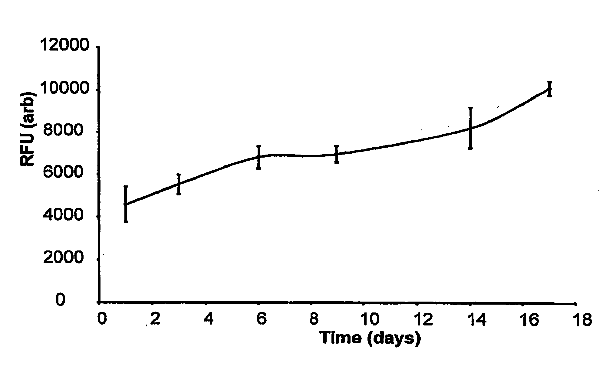
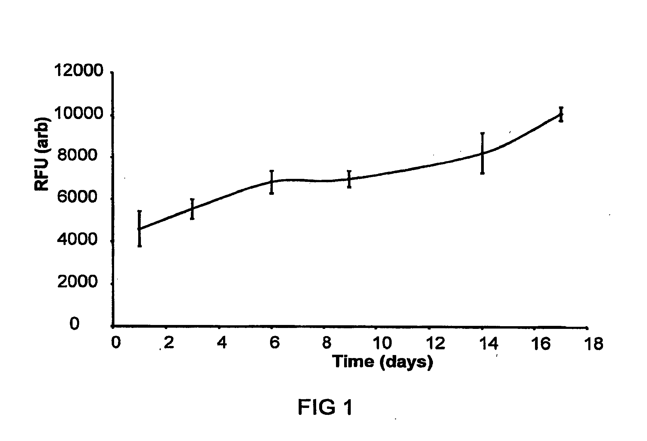
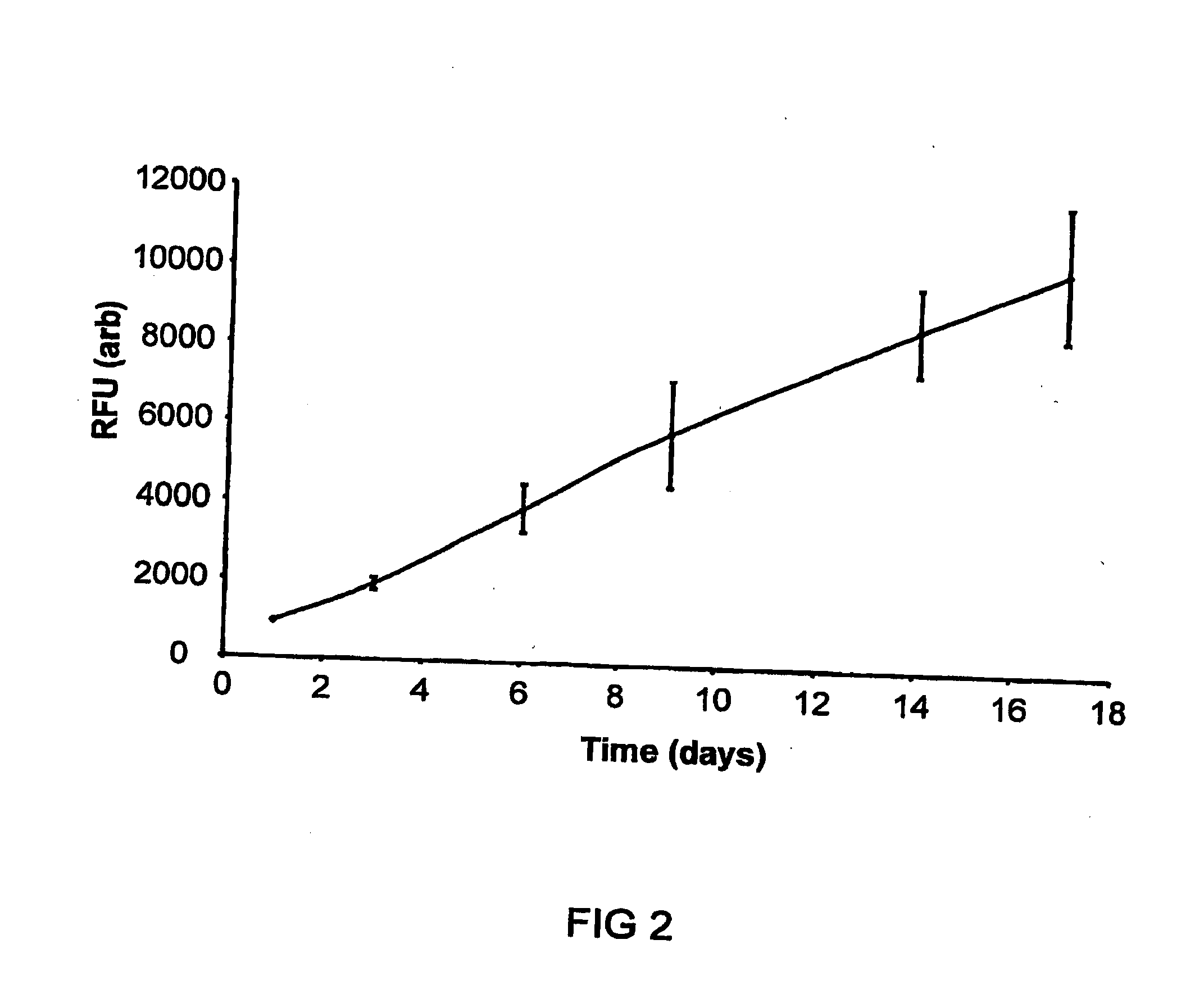
[0055]Cell growth in static culture was measured upon scaffolds (triplicate repeats) seeded with human dermal fibroblasts (and cell free controls). Ground blend material (80 mgs of 15% PEG1000 / 5050DL ground blend) was pre-sintered in a 6 mm PDMS mould at 37° C. for 15 minutes. A cell suspension was then added to the material (5×10⁵...


PUM

PropertyMeasurementUnit
porosityaaaaaaaaaa
molecular weightsaaaaaaaaaa
porosityaaaaaaaaaa

Abstract

A porous matrix suitable for use as a tissue scaffold is described. The matrix may be shaped before insertion into or at the target tissue site, or injected via a minimally invasive method. The matrix may be pre-seeded with cells of the target tissue or may be used to support growth of the local endogenous tissue. The matrix may contain growth factors or other pharmacologically acceptable moieties such as antibiotics.

Description

RELATED APPLICATION[0001]The present application is a divisional application of U.S. patent application Ser. No. 10 / 550,151 filed 29 Mar. 2004 that is a U.S. national stage of international application serial no. PCT / GB2004 / 001419 filed on 29 Mar. 2004 that claims priority to Great Britain patent application serial number 0307011.7 filed 27 Mar. 2003, each of which is incorporated herein by reference in its entirety.BACKGROUND[0002]1. Field of the Invention[0003]This invention relates to a porous matrix. More particularly, the present invention relates to porous matrices which are intended to be used in the animal body and which are formed in situ at a target tissue site.[0004]2. Related Art[0005]Many patent applications describe the use of gels or sols, especially hydrogels, for use as tissue scaffolds. For example, WO 00 / 23054 describes the use of polyvinyl alcohol microspheres in the occlusion of blood vessels or embolizations. WO 99 / 15211 and WO 00 / 64977 describe the use of hydr...

Claims


Application Information

Patent Timeline
Patent Type & Authority Applications(United States)
IPC IPC(8): A61K9/00A61L27/36A61L27/54A61L27/56
CPCA61L27/54A61L27/56A61L2300/254A61L2300/406A61L2300/414A61L2300/43A61L27/38A61P43/00A61L27/36
Inventor FRANCE, RICHARD MELVILLEQUIRK, ROBIN ANDREW
Owner REGENTEC
Why Eureka
Try Eureka