
Method for making positive photosensitive planographic printing plate

a planographic printing plate and photosensitive technology, applied in the field of making a can solve the problems of defective printing durability, large variation in the solubility of the exposed and unexposure areas, and excessive development failures, so as to reduce the variation in the sensitivity of the finished positive photosensitive planographic printing plate and reduce the drying temperature between areas.

Inactive Publication Date: 2008-10-02
FUJIFILM CORP
View PDF2 Cites 7 Cited by
  • Summary
  • Abstract
  • Description
  • Claims
  • Application Information

AI Technical Summary

Benefits of technology

[0010]The present invention has been accomplished in view of the above-described problems, and is intended to provide a method for making a positive photosensitive planographic printing plate, the method allows stable production of favorable products with a small variation in sensitivity, and a small variation in the dot size after plate making.
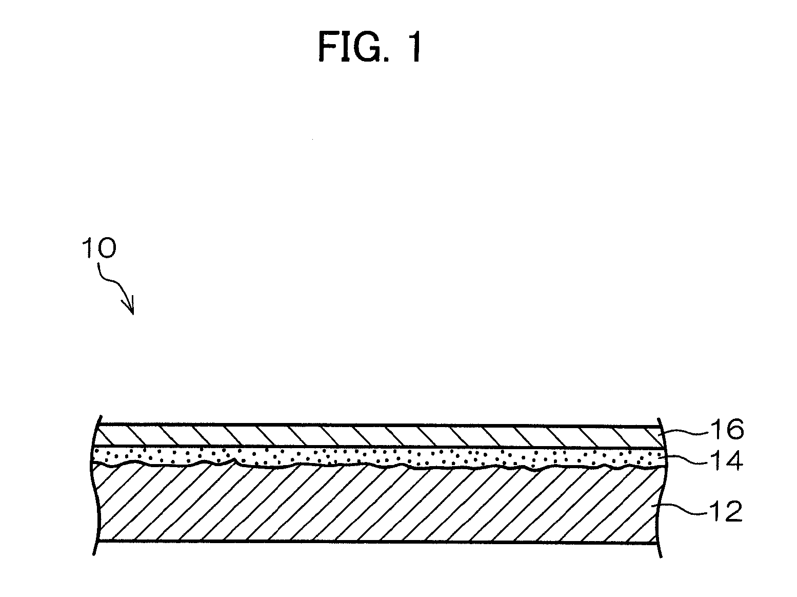
[0013]According to the present aspect, the use of the steam-containing hot air having a temperature of 90° C. to 200° C. and a relative humidity of 8% to 70% in the undercoat layer drying step allows favorable removal of the solvent with the temperature variation in the undercoat layer coating is suppressed during drying. The mechanism is that the steam is absorbed in the undercoat layer coating to increase the free volume in the coating, and resultantly the diffusion rate of the residual solvent in the coating remarkably increases to accelerate the removal of the solvent. Under the method, the undercoat layer coating is dried at a lower temperature and more quickly than a conventional hot air drying method without requiring the supply of much heat to the undercoat layer coating, whereby the temperature variation is suppressed. As a result of this, the sensitivity variation in the finished positive photosensitive planographic printing plate is reduced.
[0018]The dry point refers to a dry condition wherein the surface glossiness of the applied undercoat layer solution does not change any more. The mechanism of the removal of the residual solvent in the steam-containing hot air drying step is expressed after the undercoat layer reaches the dry point. Accordingly, the drying operation in the first drying step before the steam-containing hot air drying step reduces the time taken until the applied undercoat layer solution reaches the dry point, and more effectively removes the solvent in the steam-containing hot air drying step in comparison with the case where the steam-containing hot air is used from the beginning of the undercoat layer drying step.
[0022]According to the present aspect, the variation in the drying temperature between areas is suppressed in the undercoat layer drying step, and the variation in the sensitivity of the finished positive photosensitive planographic printing plate is reduced. In addition, the solvent is removed more quickly in comparison with the conventional drying operation using dry hot air.

Problems solved by technology

However, under the system, the difference in the degree of insolubility of the unexposed areas in the developer and solubility of the exposed areas is so small that excessive development and development failures have tended to occur.
In addition, minute surface defects caused during handling may result in defective printing durability.
In the planographic printing plate of this type, the top layer in the infrared exposed areas is dissolved and removed by alkaline water to expose the undercoat layer having high alkali solubility, which results in notable difference in the solubility of the unexposed and exposed areas.
However, the multilayered infrared laser-sensitive positive planographic printing plate has problems such as the minor differences in sensitivity between the end and center portions in the width direction of the aluminum web, and variations in sensitivity due to the changes in conditions such as the thickness of the aluminum web.
These phenomena may result in the variation in the dot size after plate making to cause printing problems.

Method used


Image

  • Method for making positive photosensitive planographic printing plate
  • Method for making positive photosensitive planographic printing plate
  • Method for making positive photosensitive planographic printing plate

Examples


example

[0079]Examples of the method for making a positive photosensitive planographic printing plate according to the present invention are described below.

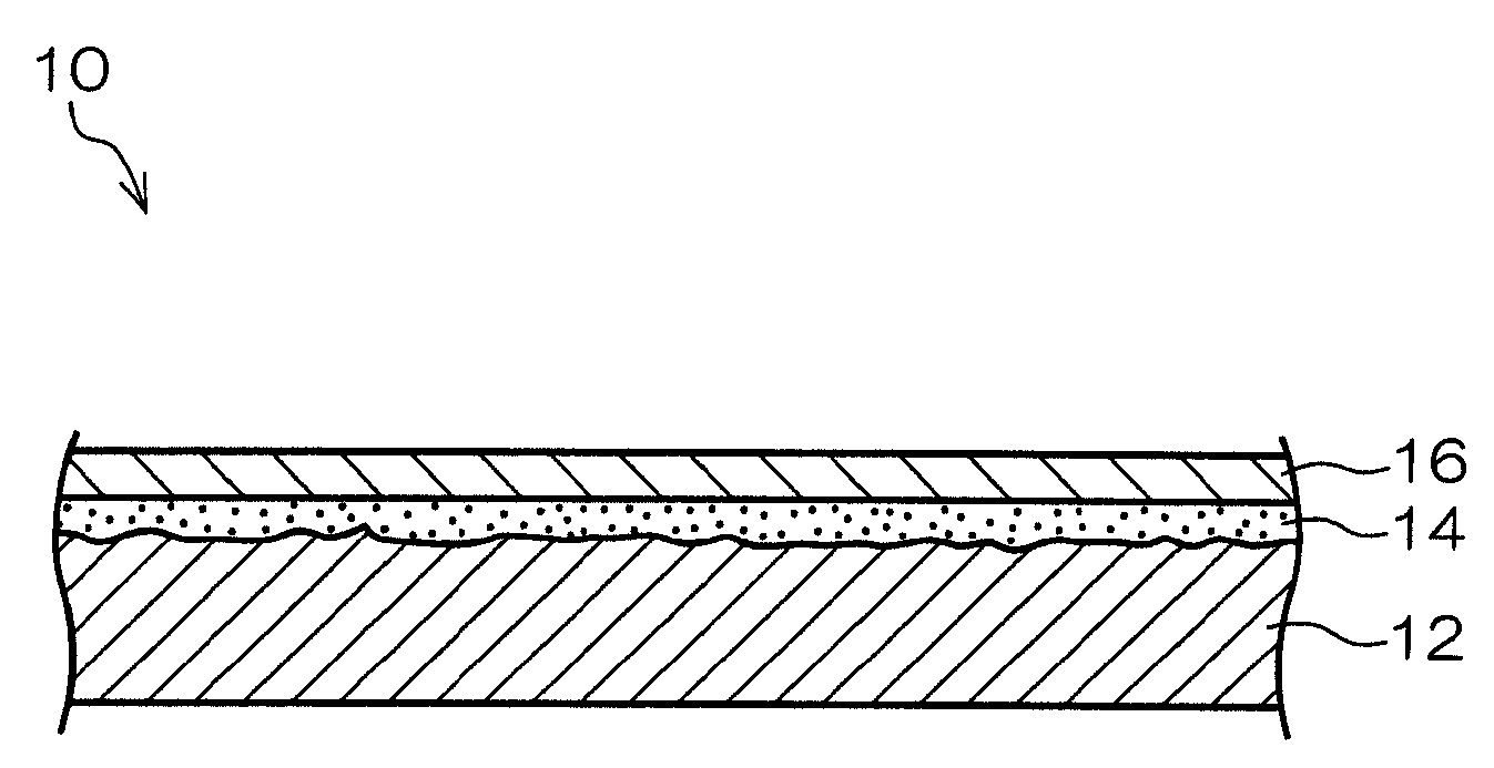
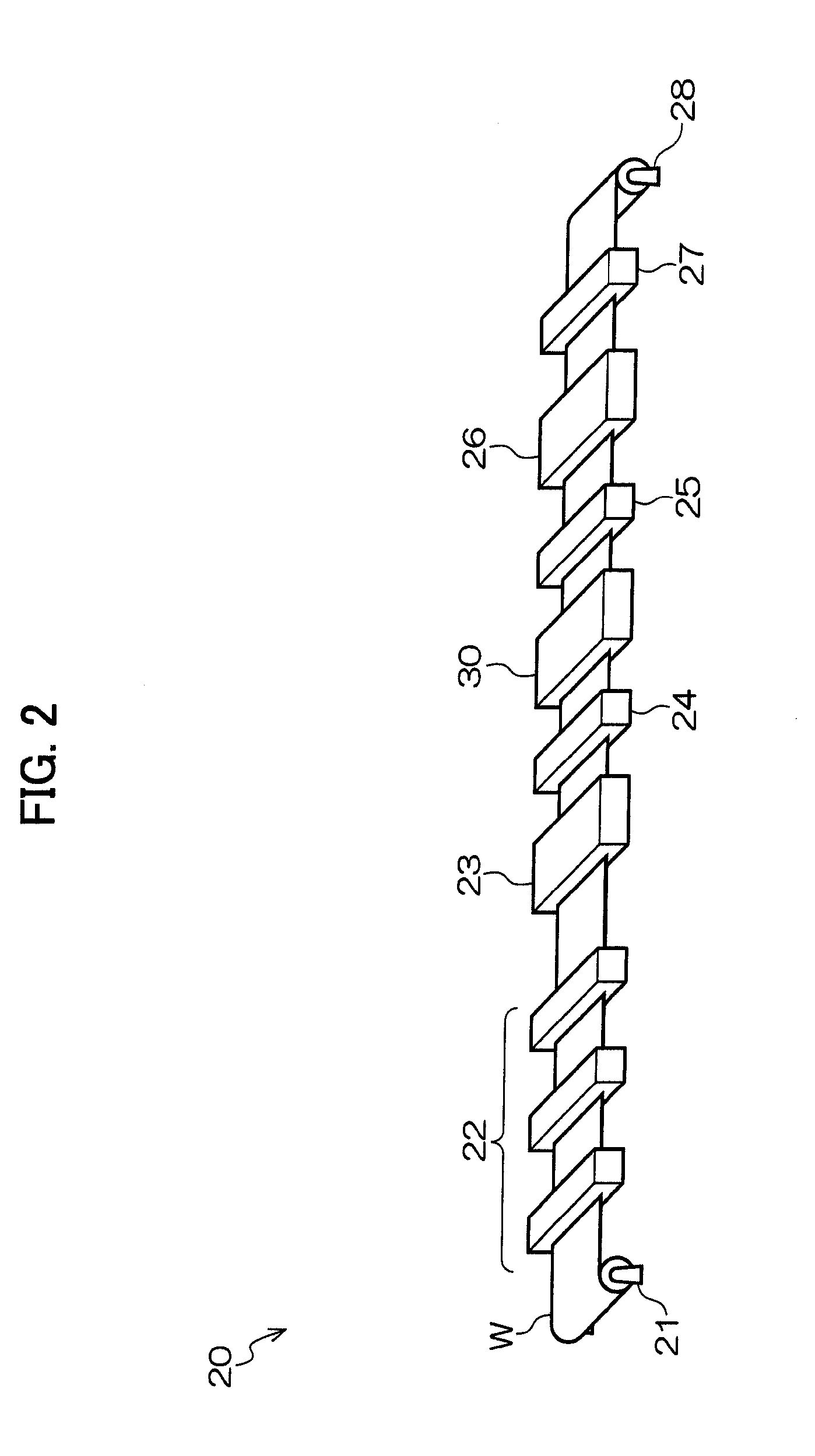
[0080]An aluminum web W having a width of 1030 mm and a thickness of 0.3 mm was subjected to surface treatment in the surface treatment unit 22, coated with a substrate in the substrate applying / drying unit 23, and then subjected to undercoat layer drying treatment in the undercoat layer applying / drying unit 30. The applied undercoat layer solution contained the acrylic resin having an alkali-soluble group and the solvent as described above, and the coating was dried under the following conditions at different temperatures and humidities. The results are shown in [Table 1]. The evaluation used a positive photosensitive planographic printing plate having a width of 1030 mm and a length of 800 mm which had been made by cutting the aluminum web W, a setter LUXCEL T-9000HS manufactured by Fujifilm Corporation, and a TAFFETA20 screen. A 50% ...


PUM


Abstract

A method for making a positive photosensitive planographic printing plate including of a base having formed thereon in this order an undercoat layer and an image recording layer, wherein the undercoat layer is obtained by applying an undercoat layer solution containing a solvent and an acrylic resin having an alkali-soluble group, followed by drying the coating, the image recording layer contains a novolac resin and an infrared absorbing agent, and the applied undercoat layer solution is dried in an undercoat layer drying step which includes a steam-containing hot air drying step using steam-containing hot air having a temperature of 90° C. to 200° C., and a relative humidity of 8% to 70%.

Description

CROSS-REFERENCE TO RELATED APPLICATION[0001]This application claims priority under 35 USC 119 from Japanese Patent Application No. 2007-087977, the disclosure of which is incorporated by reference herein.BACKGROUND OF THE INVENTION[0002]1. Field of the Invention[0003]The present invention relates to a method for making a photosensitive planographic printing plate, and specifically relates to a method for making an infrared laser-sensitive positive photosensitive planographic printing plate for so-called direct plate-making, wherein the printing plate is directly made based on digital signals output from a computer or the like.[0004]2. Description of the Related Art[0005]With the remarkable progress of lasers in recent years, high-power, small-sized solid lasers and semiconductor lasers having emission regions in the near infrared to infrared regions are now readily available. These lasers are extremely useful as light sources for making printing plates directly from digital data out...

Claims


Application Information

Patent Timeline
IPC IPC(8): B05D5/00
CPCB41C1/1016B41C2201/04B41C2201/14B41C2210/02B41C2210/06B41C2210/24B41C2210/262
Inventor TAGUCHI, TAKAOKAWAUCHI, IKUO
Owner FUJIFILM CORP
Learn More