Thermal power plant

a technology of thermal power plant and turbine, which is applied in the direction of machines/engines, mechanical energy handling, mechanical equipment, etc., can solve the problems of increasing the development cost and extending the development term, the strength of the rotational shaft (rotor) of the turbine made of stainless steel, which is currently used, and the inability to withstand, so as to improve improve the power generation efficiency. , the effect of improving the efficiency of the turbin

Inactive Publication Date: 2008-10-09
KK TOSHIBA
View PDF10 Cites 18 Cited by
  • Summary
  • Abstract
  • Description
  • Claims
  • Application Information

AI Technical Summary

Benefits of technology

[0022]The present invention has been made in view of these circumstances. The object of the present invention is to provide a thermal power plant capable of easily improving power generation efficiency, by improving turbine efficiency.

Problems solved by technology

However, when employing these arts for improving the power generation efficiency, i.e., increase of a steam temperature or elongation of a length of a last-stage moving blade, there are required not only an advanced design for fluid and strength and a cooling technique, but also a material of a high strength, which greatly increases a developing cost and extends a developing term therefor.
When the steam temperature is increased in order to attain an effective power generation, a strength of a rotational shaft (rotor) of a turbine made of a steel alloy such as stainless steel, which is currently used, cannot withstand.
However, it is difficult to manufacture a large super alloy steel ingot, and a large manufacturing cost is required therefor.
Thus, it takes a lot of time before such a super alloy can be practically applied.
Thus, further reduction in exhaust loss achieved by the further elongation of the moving blade also comes near the limit.
However, since this structure decreases a flowrate per flow, a length of the moving blade of a first half stage of the low pressure turbine, which invites deterioration in performance of the turbine.
In addition, since the number of the low pressure turbines is increased, a larger cost is necessary.
However, in the above-described steam turbine system 50 of a cross-compound type, since it is necessary to electrically synchronize the two generators 12 and 13, a complicated control system is required, resulting in deterioration in operability.
Thus, when a conventional alloy steel is used as a material for a rotational shaft, it will be difficult to increase the steam temperature in the future, in terms of the strength of the rotational shaft of the turbine 2a.

Method used


Image

  • Thermal power plant
  • Thermal power plant
  • Thermal power plant

Examples


first embodiment

[0035]A thermal power plant in a first embodiment of the present invention is described below with reference to the drawings. FIGS. 1 to 4 show a first embodiment of the present invention.

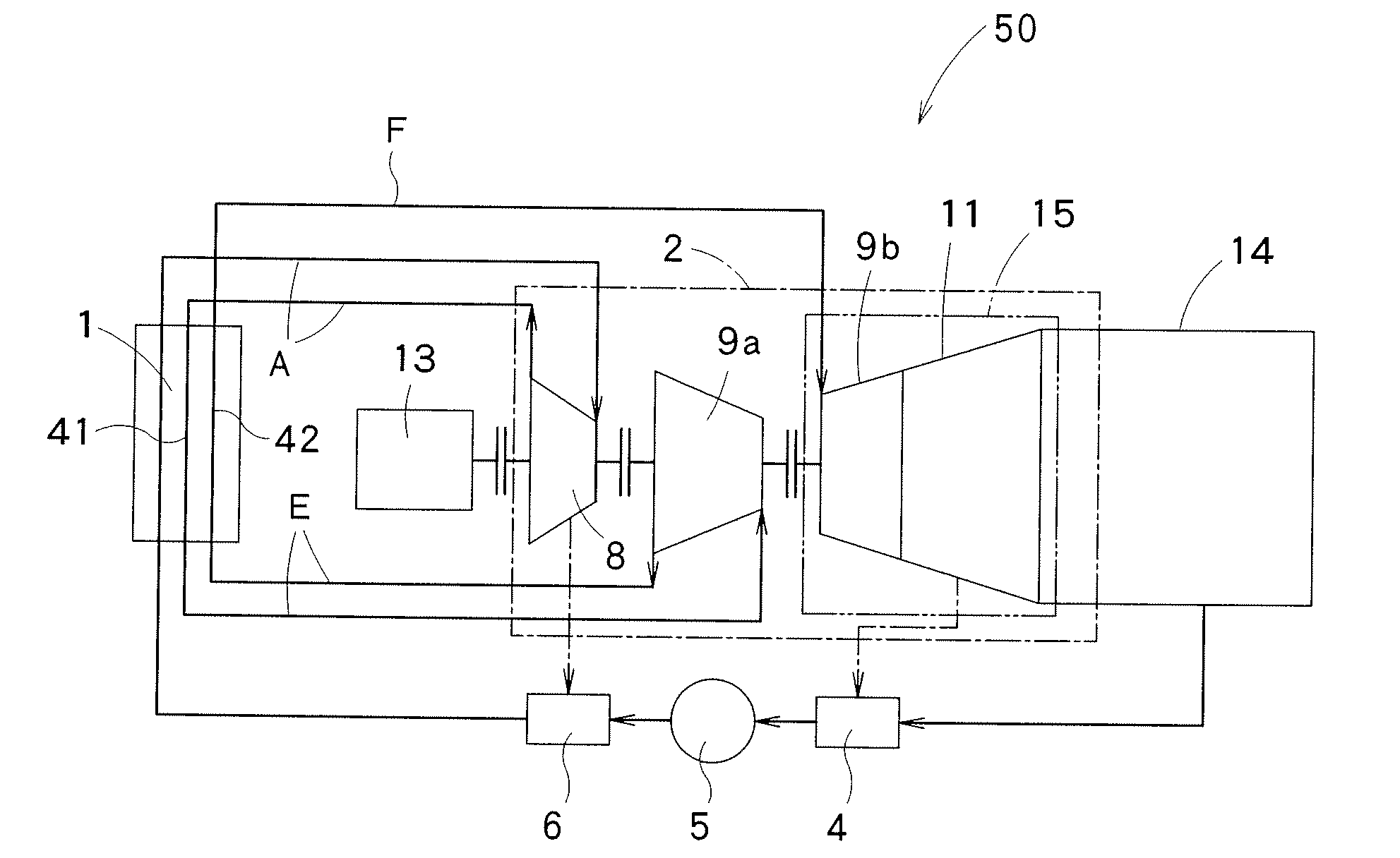
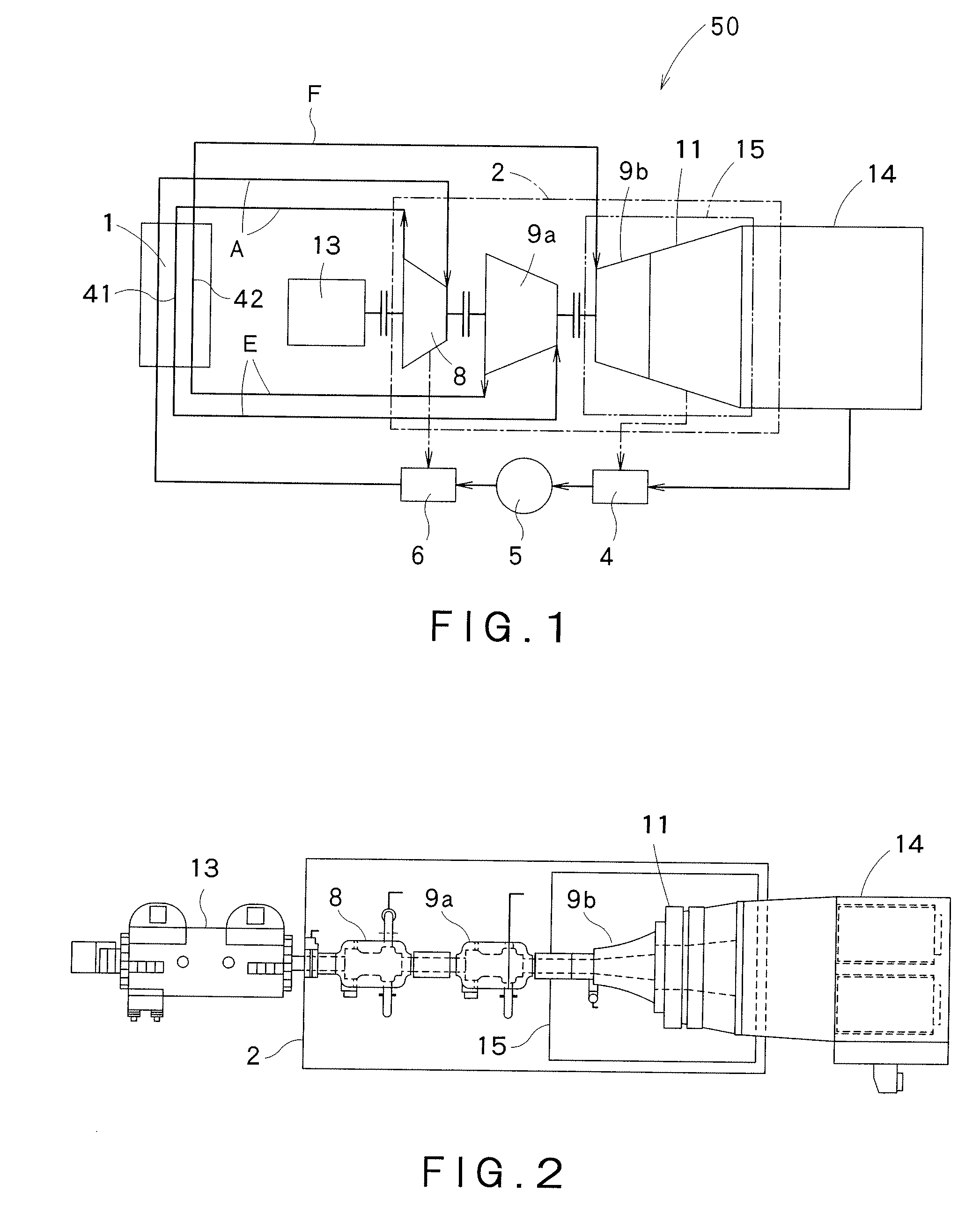
[0036]As shown in FIGS. 1 and 2, a steam turbine system 50 of a thermal power plant in a first embodiment of the present invention includes a boiler 1, a turbine 2, a condenser 14, and a 4-pole generator 13. The boiler 1 has a heater that heats a feed water by using a heat caused by combustion of a fossil fuel to generate a main steam A. In this embodiment, the boiler 1 is preferably a furnace utilizing coal or oil as a fuel. In this embodiment, the boiler 1 has a first reheater 41 and a second reheater 42, other than the heater that generates main steam A. First reheater 41 reheats the main steam A discharged from a high pressure turbine 8 so as to generate a first-stage reheated steam E. Second reheater 42 reheats the first-stage reheated steam E discharged from a first intermediate pressure turb...

second embodiment

[0098]Next, a second embodiment of the present invention is described with reference to FIGS. 5 and 6. The second embodiment shown in FIGS. 5 and 6 is a so-called combined cycle plant in which a gas turbine system 30 is combined with the steam turbine system 50 in the first embodiment shown in FIG. 1. The gas turbine system 30 includes: a compressor 31 that compresses air; a combustor 32 that burns a fossil fuel such as natural gas with the air compressed by the compressor 31 so as to generate a combustion gas; a gas turbine 33 that is driven by the combustion gas generated by the combustor 32; and a gas turbine generator 35 connected to the bas turbine 33. As a boiler for heating a feed water to generate a main steam by using a heat caused by combustion of fossil fuel, In this embodiment, steam turbine system 50 comprises heat recovery steam generator (HRSG) 20, in place of the boiler 1 in the first embodiment shown in FIG. 1. Heat recovery steam generator (HRSG) 50 has a heater th...

third embodiment

[0118]A third embodiment of the present invention is described with reference to FIGS. 7 and 8. The third embodiment shown in FIGS. 7 and 8 is a steam turbine system 50 of a single-stage reheating type, which only includes one intermediate pressure turbine 9a. In other words, steam turbine system according to this embodiment eliminates the first intermediate pressure turbine 9a from the first embodiment as shown in FIGS. 1 and 2. Other structure of this embodiment is substantially the same as that of the first embodiment shown in FIGS. 1 to 4. An intermediate pressure turbine 9 in this embodiment corresponds to the second intermediate pressure turbine 9b in the first embodiment. In this embodiment, only one reheater 45 is provided in boiler 1.

[0119]In FIGS. 7 and 8, the intermediate pressure turbine 9 and a low pressure turbine 11 received in a single casing constitutes an intermediate and low pressure turbine 15. The turbine into which a reheated steam is defined as the intermediat...


PUM


Abstract

By improving a turbine efficiency, a power generation efficiency can be easily improved. The thermal power plant of the present invention comprises, for example: a boiler 1 that heats a feed water by utilizing a heat caused by combustion of a fossil fuel so as to generate a main steam A; reheaters 41 and 42 installed in the boiler 1; a turbine 2; and a generator 13 connected to the turbine 2. The turbine 2 includes: a high pressure turbine into which the main steam A from the boiler 1 is introduced; an intermediate pressure turbine 9 into which the reheated steams E and F generated by the reheaters 41 and 42 are introduced, the intermediate pressure turbine 9 being uniaxially connected to the high pressure turbine 8; and a low pressure turbine 11 into which the reheated steams E and F discharged from the intermediate pressure turbine 9 is introduced, the low pressure turbine 11 being coupled with the high pressure turbine 8 and the intermediate pressure turbine 9. The generator 7 has more than two poles, and is coupled with the high pressure turbine 8, the intermediate pressure turbine 9, and the low pressure turbine 11.

Description

CROSS-REFERENCE TO RELATED APPLICATION[0001]This application claims priority to Japanese Patent Application No. 2007-92286 filed on Mar. 30 2007, and the whole description in Application No. 2007-92286 is incorporated herein by reference.BACKGROUND OF THE INVENTION[0002]1. Field of the Invention[0003]The present invention relates to a thermal power plant capable of improving a power generation efficiency by increasing a steam temperature and a turbine efficiency.[0004]2. Background Art[0005]Conventional thermal power plants are classified into a conventional-type thermal power plant shown in FIG. 9 including a steam turbine system 50 of a reheat regenerative Rankine cycle, and a combined thermal power plant shown in FIG. 10 in which a gas turbine system 30 and a steam turbine system 50 are combined with each other, the steam turbine system 50 being driven by using a steam heated by an exhaust gas C discharged from the gas turbine system 30.[0006]As shown in FIG. 9, the conventional-...

Claims


Application Information

Patent Timeline
Patent Type & Authority Applications(United States)
IPC IPC(8): F01K23/06
CPCF01K7/22F01K7/38F01K7/40F01K23/10Y02E20/16
Inventor KAWAKAMI, HIROSHIHATTORI, NOBUHIKO
Owner KK TOSHIBA
Why Eureka
Try Eureka