Wavefront aberration measuring device, projection exposure apparatus, method for manufacturing projection optical system, and method for manufacturing device

a technology of exposure apparatus and measurement device, which is applied in the direction of optical apparatus testing, printing, instruments, etc., can solve the problems of insufficient luminance of interference fringe, insufficient light amount of measuring light beam, and difficulty in detecting

Inactive Publication Date: 2008-10-09
NIKON CORP
View PDF20 Cites 9 Cited by
  • Summary
  • Abstract
  • Description
  • Claims
  • Application Information

AI Technical Summary

Benefits of technology

[0012]According to the first aspect exemplifying the present invention, the wavefront aberration measuring device is realized, which makes it possible to reliably obtain the information about the wavefront aberration of the inspection-objective optical system.
[0014]According to the second aspect exemplifying the present invention, the wavefront aberration measuring device is realized, which makes it possible to reliably obtain the information about the wavefront aberration of the inspection-objective optical system.
[0016]According to the third aspect exemplifying the present invention, the projection exposure apparatus is realized, which makes it possible to reliably obtain the information about the wavefront aberration of the projection optical system.
[0018]According to the fourth aspect exemplifying the present invention, the method for manufacturing the projection optical system is realized, which makes it possible to reliably manufacture the high performance projection optical system.
[0020]According to the fifth aspect exemplifying the present invention, the device can be manufactured by using the exposure apparatus which makes it possible to satisfactorily expose the substrate.

Problems solved by technology

Therefore, when the light is restricted by the pin hole, then the light amount of the measuring light beam is insufficient, and the luminance of the interference fringe is insufficient as well.
Therefore, it is difficult to effect the detection.
The wavefront of the light generated by the slit does not form an ideal spherical surface in the longitudinal direction of the slit.
However, it is impossible to fill the entire pupil of the inspection-objective optical system with the measuring light beam, because the slit does not diffract the light in the longitudinal direction.
In such a situation, it is impossible to bring about any satisfactory interference fringe which includes the necessary information.
However, in this case, the load is increased upon the design of the illumination system.

Method used


Image

  • Wavefront aberration measuring device, projection exposure apparatus, method for manufacturing projection optical system, and method for manufacturing device
  • Wavefront aberration measuring device, projection exposure apparatus, method for manufacturing projection optical system, and method for manufacturing device
  • Wavefront aberration measuring device, projection exposure apparatus, method for manufacturing projection optical system, and method for manufacturing device

Examples


first embodiment

[0040]A first embodiment is explained. This embodiment relates to a projection exposure apparatus for EUVL provided with the function to measure the wavefront aberration. The wavefront aberration is measured, for example, at an appropriate timing during the operation of the projection exposure apparatus.

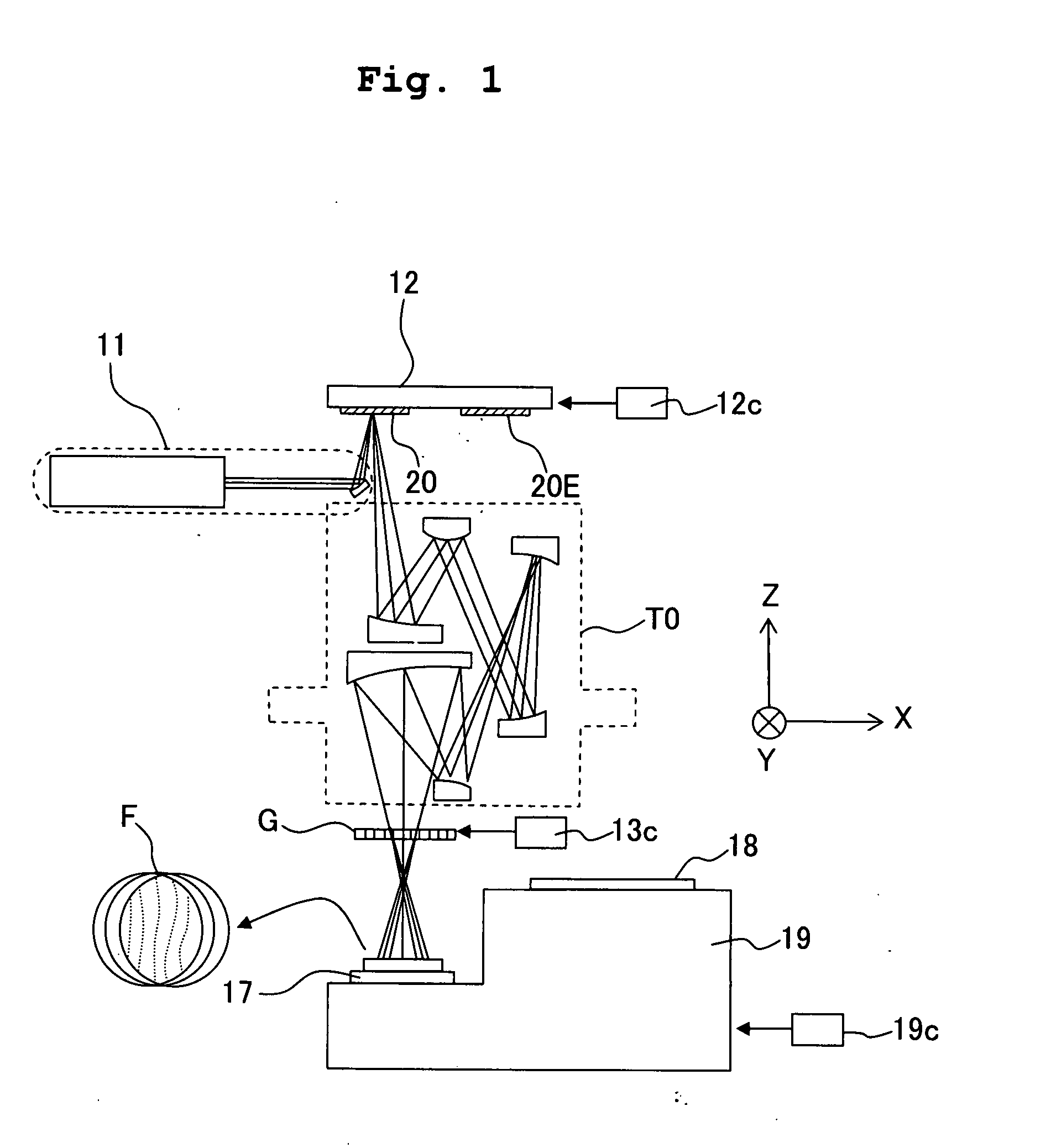
[0041]FIG. 1 shows a schematic arrangement of the apparatus of this embodiment.

[0042]As shown in FIG. 1, the apparatus of this embodiment includes an illumination optical system 11 for EUVL, a mask stage 12, a measuring reflection type mask 20, a driving mechanism 12c for the mask stage, a projection optical system TO for EUVL, a diffraction grating G, a driving mechanism 13c for the diffraction grating, a CCD image pickup element 17, a wafer stage 19, a driving mechanism 19c for the wafer stage, and the like.

[0043]The measuring reflection type mask 20 is supported, for example, by the mask stage 12 together with an exposure reflection type mask 20E, and is inserted into the optical ...

second embodiment

[0070]A second embodiment will be explained. Only the difference from the first embodiment will now be explained. The difference between the second and first embodiments is in the aperture pattern of the measuring reflection type mask 20. The aperture pattern to be used when the shear direction is the X direction and the aperture pattern to be used when the shear direction is the Y direction are different from each other in only the direction of arrangement by 90°. Therefore, only the former will now be explained.

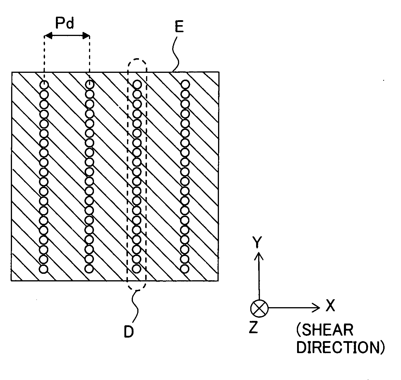
[0071]FIG. 3 illustrates the aperture pattern (for the measurement in the X direction) of this embodiment. The area E indicates an area corresponding to one object point as the measurement objective.

[0072]As shown in FIG. 3, in this aperture pattern, a plurality of dot groups D, which are aligned linearly in the non-shear direction (Y direction), are periodically arranged in the shear direction (X direction) with spacing distances.

[0073]An arrangement pitch Pd of the dot gr...

third embodiment

[0084]A third embodiment will be explained. Only the difference from the second embodiment will now be explained. The difference between the third and second embodiments is in the aperture pattern of the measuring reflection type mask 20. The aperture pattern to be used when the shear direction is the X direction and the aperture pattern to be used when the shear direction is the Y direction are different from each other in only the direction of arrangement by 90°. Therefore, only the former will now be explained.

[0085]FIG. 5 illustrates the aperture pattern (for the measurement in the X direction) of this embodiment. An area E indicates an area corresponding to one object point as the measurement objective.

[0086]As shown in FIG. 5, in the aperture pattern of this embodiment, a plurality of groups of dots (dot groups) D, which are aligned in a band-shaped form long in the non-shear direction (Y direction), are periodically arranged with spacing distances therebetween in the shear di...


PUM


Abstract

A wavefront aberration measuring device includes a mask which arranges a group of minute apertures for generating a group of point light sources at an object point as a measurement objective of an inspection-objective optical system, an illumination system which illuminates the mask with an illumination light, a diffraction grating which shears, into a plurality of light fluxes, a light flux exiting from the group of minute apertures and passing via the inspection-objective optical system, and a detecting portion which detects an interference fringe formed mutually by the plurality of sheared light fluxes, wherein a center spacing distance L between adjacent minute apertures which are adjacent in a shear direction in the group of minute apertures is defined to minimize the coherence degree.

Description

BACKGROUND OF THE INVENTION[0001]1. Field of the Invention[0002]The present invention relates to a wavefront aberration measuring device for measuring the wavefront aberration of an optical system including, for example, a projection optical system for EUVL (Extreme Ultra-Violet Lithography), a projection exposure apparatus which is provided with a projection optical system, a method for manufacturing a projection optical system, and a method for manufacturing a device.[0003]2. Description of the Related Art[0004]The projection optical system for EUVL is mainly constructed of those based on the catoptric type. Therefore, it is assumed that the principle of the shearing interference is applied to the measurement of the wavefront. aberration (see, for example, Japanese Patent Application Laid-open No. 2003-86501).[0005]In this wavefront aberration measurement, a mask is arranged on the object plane of an optical system to be inspected (inspection-objective optical system). A minute ap...

Claims


Application Information

Patent Timeline
Patent Type & Authority Applications(United States)
IPC IPC(8): G03B27/54G01B11/00
CPCG03F7/706G01M11/0264G01M11/0271G03F7/70258
Inventor OTAKI, KATSURA
Owner NIKON CORP
Why Eureka
Try Eureka