Adaptive and reconfigurable system for DC motor control

a dc motor and reconfigurable technology, applied in the direction of electronic commutators, dynamo-electric converter control, instruments, etc., can solve the problems of inability to meet all system requirements, lack of dexterity, and awkward current manual instrumentation

Active Publication Date: 2008-10-09
THE JOHN HOPKINS UNIV SCHOOL OF MEDICINE
View PDF9 Cites 30 Cited by
  • Summary
  • Abstract
  • Description
  • Claims
  • Application Information

AI Technical Summary

Benefits of technology

[0008]The above-described problems are addressed and a technical solution achieved in the art by providing an integrated circuit for controlling a DC motor, which is hereby disclosed. The integrated circuit includes at least one digital position and speed circuit (DPS) for providing measurements of speed, position, and direction of the motor, the DPS being in signal communication with the motor for receiving a pair of signals having a quadrature relationship; and at least one programmable gain amplifier (PGA) electrically coupled to the motor, the PGA being configured to receive a feedback signal indicative of the current flowing through the motor and to apply a second signal to regulate the speed of the motor. The integrated circuit can be incorporated into a larger motor control loop which further includes one or more power amplifiers that sum the desired motor speed with the feedback signal from the PGA; a resistor and buffer amplifier for sensing the output current of the motor; and a processor or other digital logic for providing system control signals and for receiving the measurements of speed, position, and direction of the motor. The power amplifier may also contain an input signal that specifies the maximum motor current. The integrated circuit is configured to control the speed, the torque, or the position of the motor.
[0009]The DPS includes the circuitry for measuring the position of the motor and the speed of the motor based on either frequency counting or period counting. The circuitry for measuring position of the motor includes a QDECODER circuit block for decoding the pair of signals having a quadrature relationship to an UP or DOWN signal for providing an indication of the direction of rotation of the motor and for providing a count signal indicative of a quadrature pulse count; an UP/DOWN synchronous counter electrically coupled to the QDECODER circuit block for counting the quadrature pulse count; and a parallel in-serial out register (PISO) electrically coupled to the UP/DOWN synchronous counter for serializing the quadrature pulse count so as to provide an indication of motor position. The circuitry for measuring the speed of the motor based on frequency counting includes a toggle flip flop for receiving a fixed time pulse; a counter electrically coupled to the toggle flip flop, the toggle flip flop enabling the counter for a fixed period of time, the c...

Problems solved by technology

Current manual instrumentation is awkward, hard to manipulate precisely, and lacks sufficient dexterity to permit common surgical subtasks such as suturing vocal fold tissue.
Several commercially available motion controllers and amplifiers were evaluated, but none of them satisfied all of the system requirements.
One major difficulty was that even the small (low power) amplifiers were rated at several Amps and would therefore provide motor current feedback signals th...

Method used


Image

  • Adaptive and reconfigurable system for DC motor control
  • Adaptive and reconfigurable system for DC motor control
  • Adaptive and reconfigurable system for DC motor control

Examples


Embodiment Construction

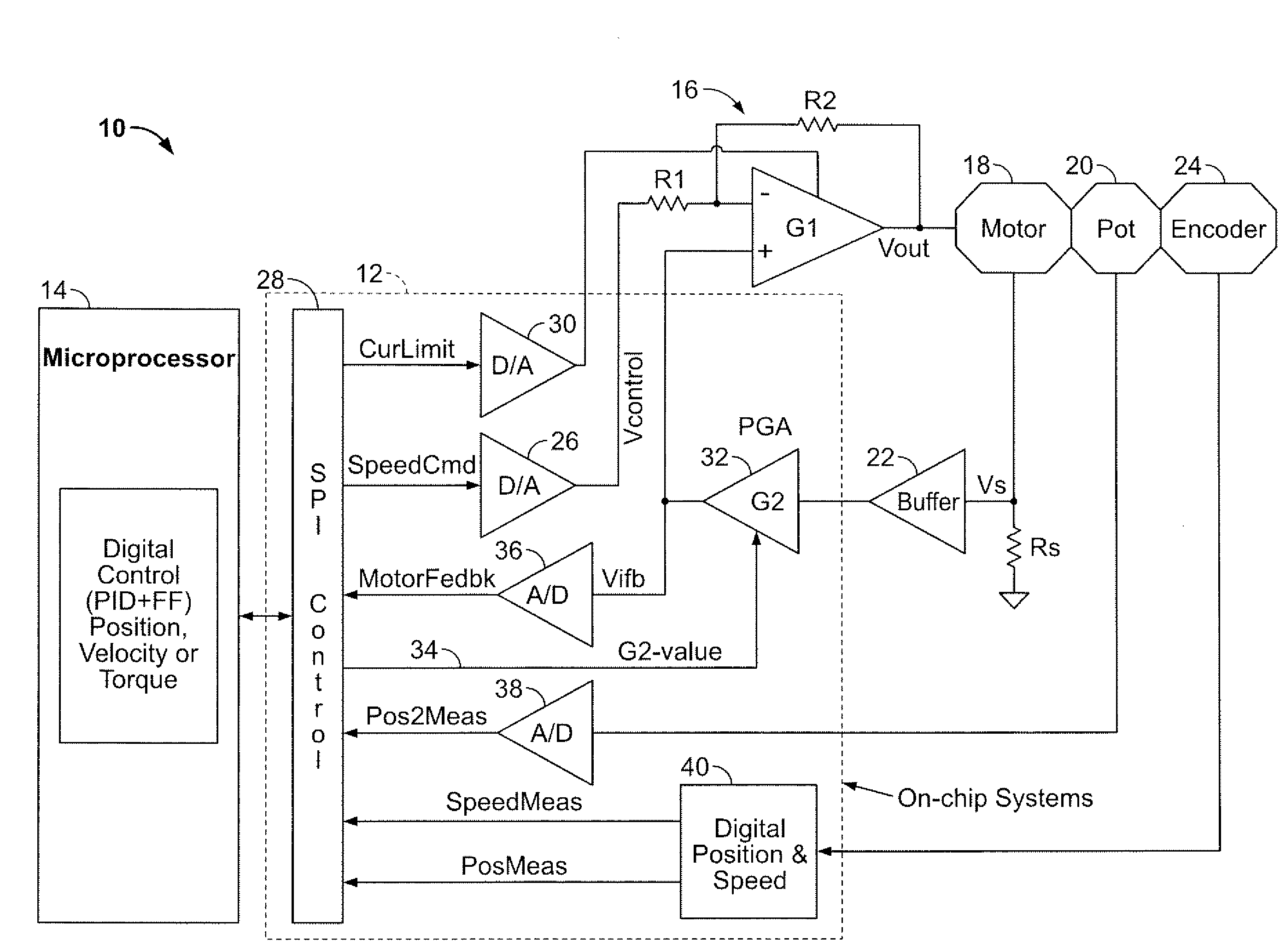
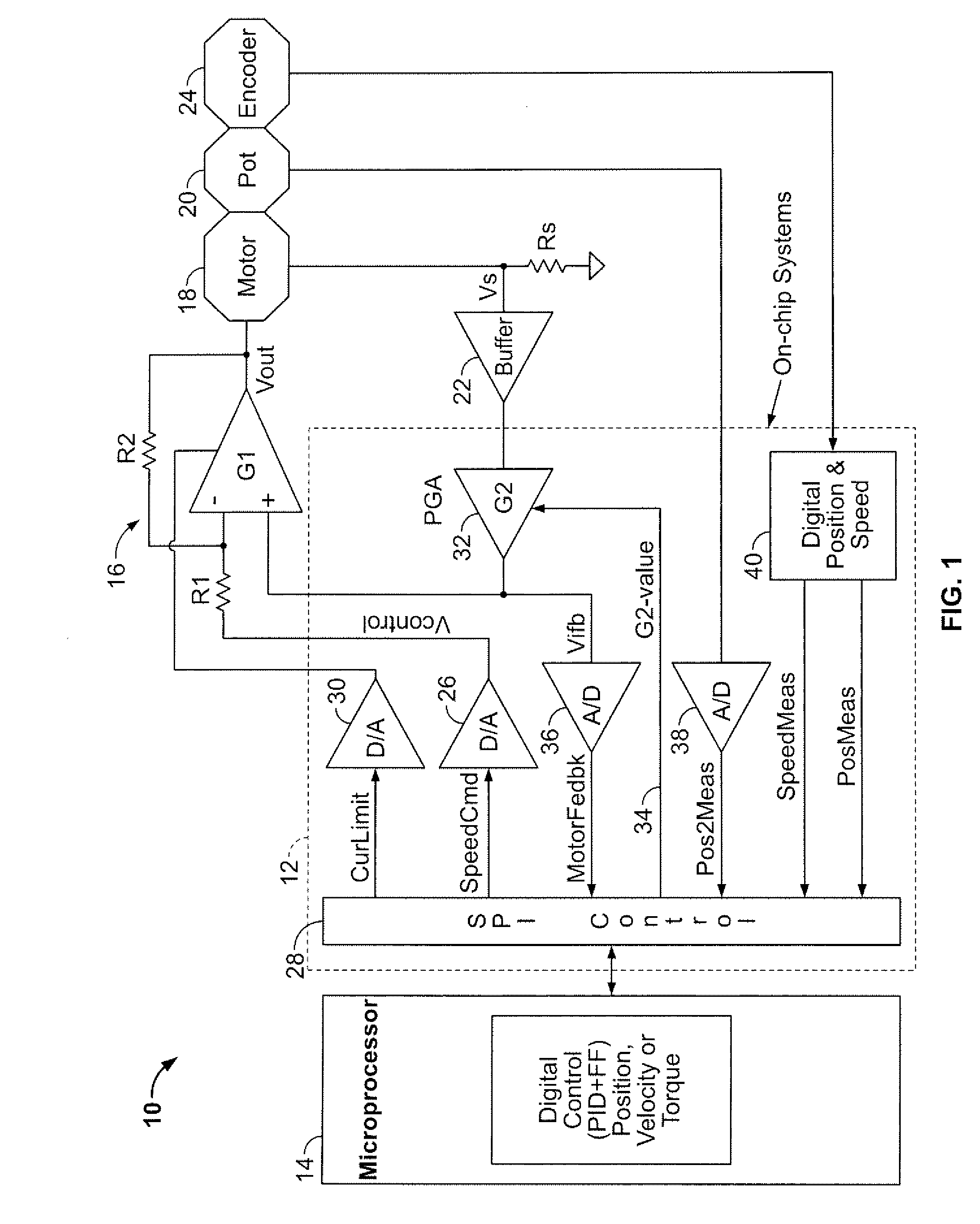
[0022]FIG. 1 is an electrical schematic diagram of a motor control circuit 10, constructed in accordance with an embodiment of the present invention. The motor control circuit 10 includes a mixed analog / digital control / measurement circuit block 12, implemented as a VLSI integrated circuit chip, a supervisory microprocessor 14 digitally coupled to the control / measurement circuit block 12, an external amplifier 16 whose inverting input Vcontrol is controlled by an analog voltage supplied by the control / measurement circuit block 12, a DC motor 18 whose initial position is set by an absolute analog sensor, such as a potentiometer, 20 and whose armature current is sensed by a buffer / sensor 22, the buffer / sensor 22 providing a feedback signal to the control / measurement circuit block 12, and an incremental encoder 24 that is optically coupled to the motor 18 and provides one of a pair of digital quadrature signals to the control / measurement circuit block 12. The control / measurement circuit...


PUM


Abstract

An integrated circuit for controlling a DC motor is disclosed. The integrated circuit includes at least one digital position and speed circuit (DPS) for providing measurements of speed, position, and direction of the motor, the DPS being in signal communication with the motor for receiving a pair of signals having a quadrature relationship; and at least one programmable gain amplifier (PGA) electrically coupled to the motor, the PGA being configured to receive a feedback signal indicative of current flowing through the motor and to apply a second signal to the motor for adjusting the speed of the motor; and at least two analog-to-digital converters (A/D), one A/D being used to quantize the output of the PGA for an off-chip processor; and another A/D to provide motor reference position from an analog sensor, such as a potentiometer; and at least two digital-to-analog converters (D/A), one D/A used to set the motor voltage; and another D/A used to set the motor current limit. The integrated circuit can be incorporated into a larger motor control loop which further includes a summing amplifier for providing the feedback signal to the motor that is indicative of current flowing through the motor; a buffer amplifier electrically for sensing the output current of the motor, and a processor for providing control signals to the system monolithic module and for receiving the measurements of speed, position, and direction of the motor.

Description

CROSS-REFERENCE TO RELATED APPLICATIONS[0001]This application claims the benefit of U.S. provisional patent application No. 60 / 922,260 filed Apr. 6, 2007, the disclosure of which is incorporated herein by reference in its entirety.FIELD OF THE INVENTION[0002]The present invention relates generally to DC motor control, and more particularly to a reconfigurable and adaptive mixed analog / digital integrated circuit for controlling and measuring the speed, position, and torque of DC motors.BACKGROUND OF THE INVENTION[0003]Robots are becoming prevalent in 21st century industrial and post-industrial societies. Robots find uses in industrial assembly, the military, toys, and in medicine. In the case of medicine, there are many applications that employ a robot comprising multiple, relatively low speed DC motors for control of surgical instruments. One such surgical application is for throat surgery. Minimally invasive surgery (MIS) of the throat is characterized by insertion of endoscopes an...

Claims


Application Information

Patent Timeline
IPC IPC(8): H02P7/28
CPCH02P6/165H02P6/17
Inventor KAZANZIDES, PETEREKEKWE, NDUBUISI JOHNETIENNE-CUMMINGS, RALPH
Owner THE JOHN HOPKINS UNIV SCHOOL OF MEDICINE
Why Eureka
Try Eureka