Reaction Vessel, Reaction Vessel Liquid Introducing Device, Liquid Introducing and Reaction Measuring Device, and Liquid Introducing Device

a technology of reaction vessel and introducing device, which is applied in the direction of gas-gas reaction process, laboratory glassware, instruments, etc., can solve the problems of complex temperature instructions, large-scale and complex devices, and complex temperature changes

Inactive Publication Date: 2008-10-09
UNIVERSAL BIO RESEARCH CO LTD
View PDF3 Cites 41 Cited by
  • Summary
  • Abstract
  • Description
  • Claims
  • Application Information

AI Technical Summary

Benefits of technology

[0016]Accordingly, the present invention has been achieved in order to solve the problems mentioned above, and a first object thereof is in providing a reaction vessel, a reaction vessel liquid introducing device, a liquid introducing and reaction measuring device, and a liquid introducing device wherein temperature control of a liquid stored within the vessel can be performed with a high accuracy and faithful responsiveness.
[0017]A second object is in providing a reaction vessel, a reaction vessel liquid introducing device, a liquid introducing and reaction measuring device, and a liquid introducing device in which the process can be quickly performed by shortening the time from when a heating or cooling instruction is given until the liquid temperature is uniformly distributed.

Problems solved by technology

Consequently, until the reaction liquid within the vessel is heated or cooled, as well as a long time being taken to reach a uniform temperature distribution in the liquid temperature due to the large capacity of the vessel, complex temperature changes occur as a result of the differences in the heat capacity or the specific heat of the housing section and the vessel, and there is a problem in that complex temperature instructions need to be performed in order to perform DNA amplification at a high accuracy.
However, these apparatuses are large-scale and complex devices in that they are provided with complex flow passages, or used large-scale centrifugal devices, and the like.

Method used


Image

  • Reaction Vessel, Reaction Vessel Liquid Introducing Device, Liquid Introducing and Reaction Measuring Device, and Liquid Introducing Device
  • Reaction Vessel, Reaction Vessel Liquid Introducing Device, Liquid Introducing and Reaction Measuring Device, and Liquid Introducing Device
  • Reaction Vessel, Reaction Vessel Liquid Introducing Device, Liquid Introducing and Reaction Measuring Device, and Liquid Introducing Device

Examples


first embodiment

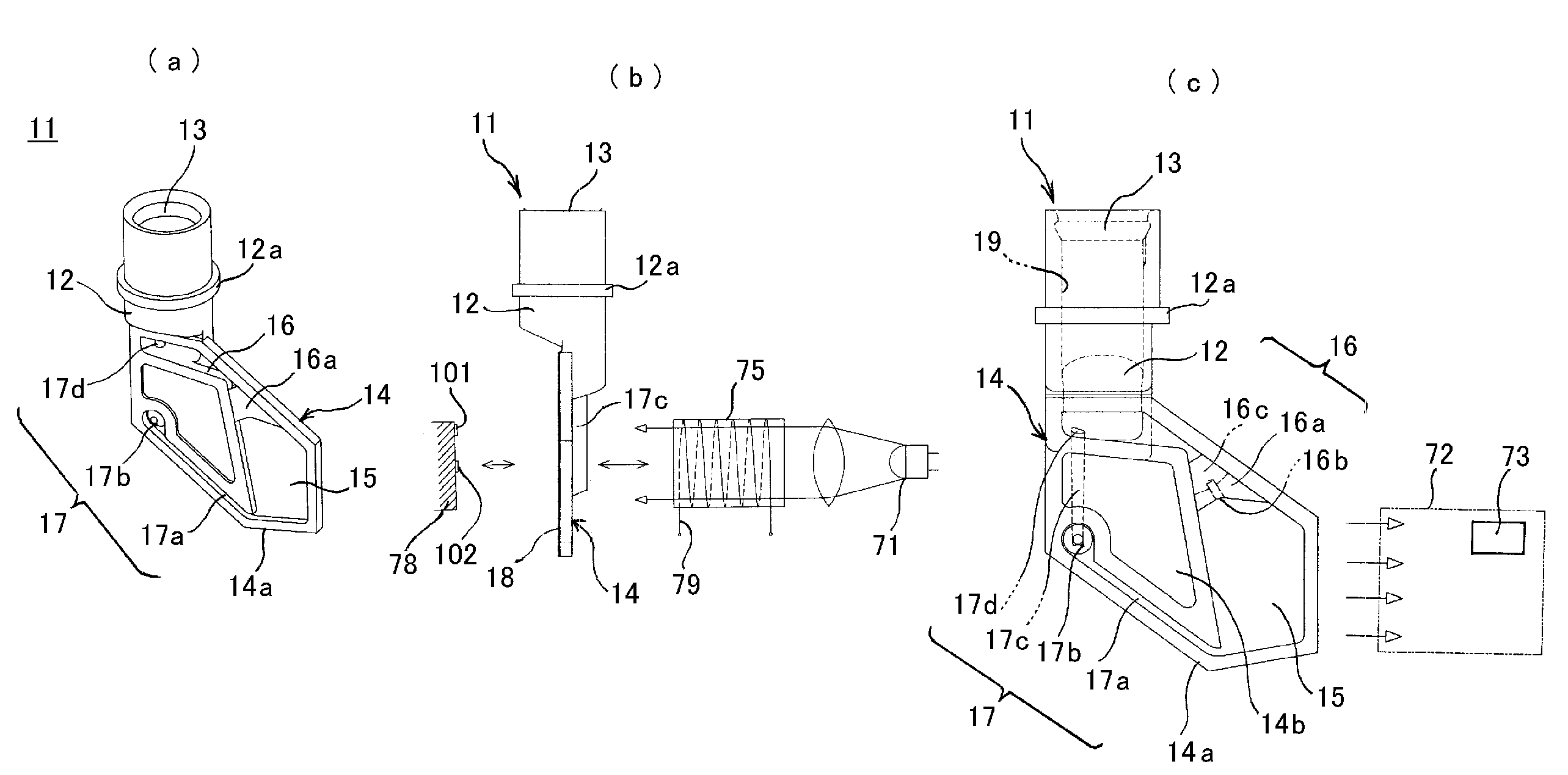
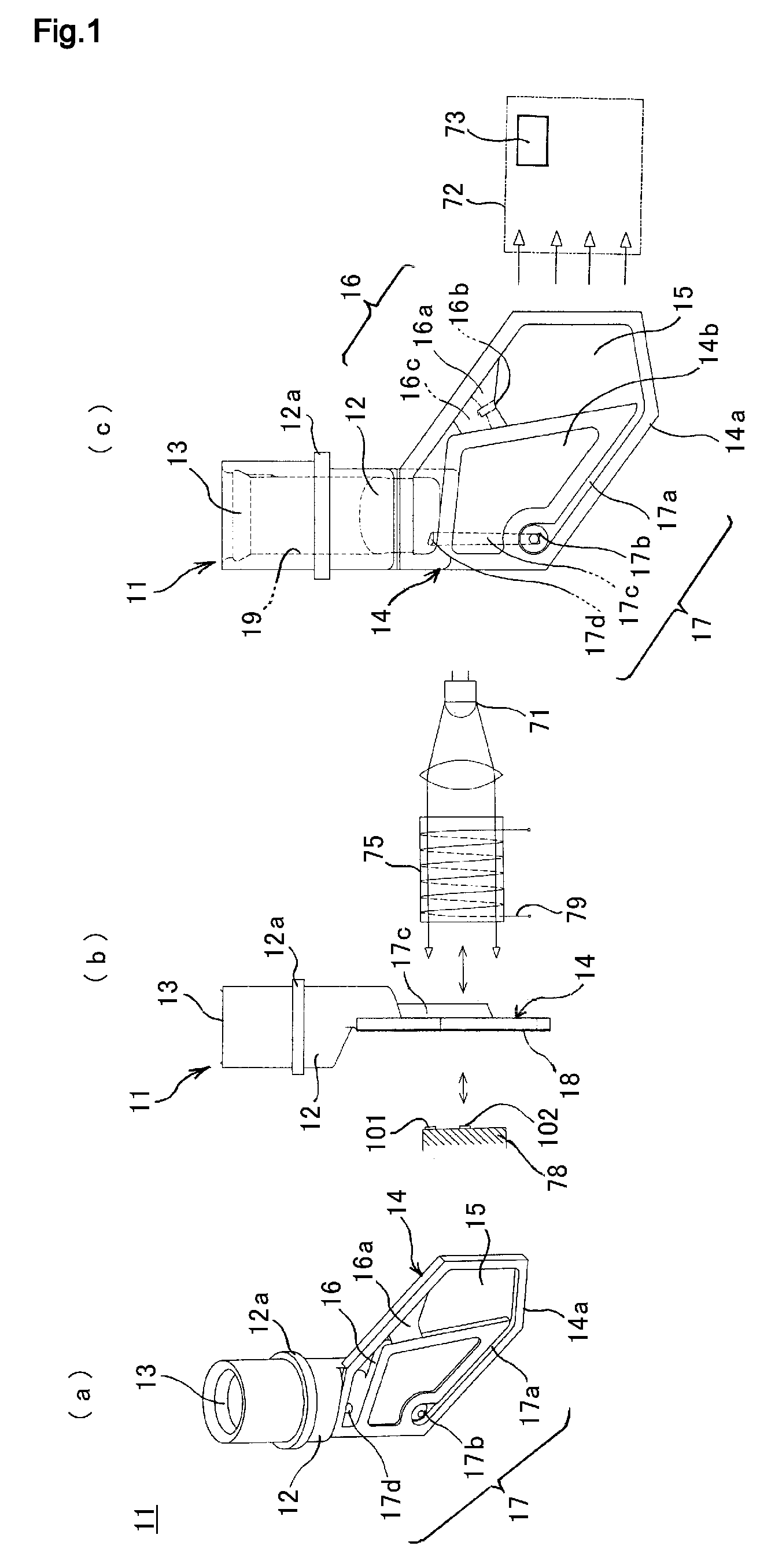
[0231]FIGS. 1 (a), (b), and (c) are a perspective view, a side view, and a front view showing a reaction vessel 11 according to the present invention. In FIGS. 1 (a) and (c), in order to clearly show the interior, it is shown in a state where a transparent film 18, which forms a portion thereof and is a soft material, is removed.

[0232]As shown in FIG. 1 (a), the reaction vessel 11 comprises: a cylindrical storage chamber 12 in which liquid is storable, which has an opening part 13 in the upper section; a reaction chamber 15 that is communicated with the storage chamber 12 via a liquid introduction flow passage 16 and a discharge flow passage 17 and is formed thinner than the storage chamber 12; and the liquid introduction flow passage 16, and the discharge flow passage 17. The liquid introduction flow passage 16, the discharge flow passage 17, and the reaction chamber 15 are formed in an approximate layer form that sandwiches the same, and the entirety thereof is a translucent react...

second embodiment

[0244]FIG. 5 shows a reaction vessel 11a according to a The reaction vessel 11a differs from the reaction vessel 11 mentioned above in that by providing a rotation supporting axle 14c along the axis of the opening part 13 of the storage chamber 12 on the underside of the reaction section 14 of the reaction vessel 11a, prevention of core deviation at the time of rotation can be achieved.

[0245]Next, the reaction vessel, which belongs in a category wherein liquid is introduced by the suction and discharging of a nozzle, is explained based on FIG. 6 and FIG. 7.

third embodiment

[0246]FIG. 6 shows a reaction vessel 31 according to a

[0247]FIG. 6 (a) shows a perspective view of the reaction vessel 31, FIG. 6 (b) is a front view thereof, FIG. 6 (c) is a cross-sectional side view thereof, FIG. 6 (d) is an enlarged cross-sectional view of region F shown in FIG. 6 (c), and FIG. 6 (e) is an enlarged perspective view of a partial portion shown in FIG. 6 (d).

[0248]The reaction vessel 31 comprises a cylindrical storage chamber 32 that has a thick diameter, a diamond-shaped prismatic reaction chamber 33 that is formed thinner than the storage chamber 32, and a thin diameter section 34 provided on the lower side of the reaction chamber 33 that is formed thinner than the cylinder.

[0249]An interval between the storage chamber 32 and the reaction chamber 33, and an interval between the reaction chamber 33 and the exterior, are connected by a flow passage 32c, and a thin diameter section 34, respectively. Consequently, in regard to the reaction vessel 31 according to the p...


PUM

PropertyMeasurementUnit
widthaaaaaaaaaa
thicknessaaaaaaaaaa
thicknessaaaaaaaaaa

Abstract

The invention relates to a reaction vessel, a reaction vessel liquid introducing device, a liquid introducing and reaction measuring device, and a liquid introducing device, and is directed to being able to perform temperature control of a liquid stored within the reaction vessel with a high accuracy and faithful responsiveness. The reaction vessel comprises: a storage chamber in which a liquid is storable, that has an opening part; a reaction chamber that is formed thinner or narrower than the storage chamber; and at least one flow passage that communicates between the storage chamber or the exterior and the reaction chamber. The reaction vessel is formed such that it is connectable to a liquid introducing section provided externally, and the liquid can be introduced into the reaction chamber by connecting to the liquid introducing section.

Description

TECHNICAL FIELD[0001]The present invention relates to a reaction vessel, a reaction vessel liquid introducing device, a liquid introducing and reaction measuring device, and a liquid introducing device.BACKGROUND ART[0002]In recent years, the polymerase chain reaction (PCR) method is used in all biology related fields as a DNA amplification method that quickly and easily amplifies specific DNA fragments. The PCR method is a method that designs two primers that are complementary to the template DNA, and reproduces the area between the primers thereof within a test tube (in vitro). The method obtains the PCR products by exponentially amplifying the DNA by repeating temperature cycles wherein a reaction solution containing complementary DNA, primers, nucleotides, and thermostable DNA polymerase is incubated at various temperatures.[0003]A single cycle comprises, with respect to a vessel charged with complementary DNA, the primer, DNA polymerase, nucleotides, and a reaction buffer solut...

Claims


Application Information

Patent Timeline
Patent Type & Authority Applications(United States)
IPC IPC(8): G01N21/00G01N21/01B01L11/00B01J19/00B01L99/00C12M1/00G01N35/08G01N37/00
CPCB01L3/0275B01L3/502B01L3/5021B01L2200/0621B01L2400/0409B01L2400/0487B01L2400/0655G01N21/03
Inventor TAJIMA, HIDEJI
Owner UNIVERSAL BIO RESEARCH CO LTD
Why Eureka
Try Eureka