Electronic height control system for a vehicle with multiple input signals

a technology of electronic height control and input signal, which is applied in the direction of transportation items, cycle equipment, instruments, etc., can solve the problems of most commonly used height control valves, regardless of their valve structure, being susceptible to “freezing” and damage, and achieve the effect of improving the control of the vehicle suspension system

Inactive Publication Date: 2008-10-16
HALDEX BRAKE
View PDF45 Cites 46 Cited by
  • Summary
  • Abstract
  • Description
  • Claims
  • Application Information

AI Technical Summary

Benefits of technology

[0011]Accordingly, it is desired to provide an electronic height control s

Problems solved by technology

The most commonly used height control valves, regardless of their valve structure, are subject to damage because of the mechanical coupling between the trailing arm and the height control valve.
The mechanical coupling is directly exposed to the environment of the trailing arm suspension, which can be very harsh.
Additionally, most of the mechanically operated valves are susceptible to “freezing” if not used regularly.
However, the system taught in Su

Method used


Image

  • Electronic height control system for a vehicle with multiple input signals
  • Electronic height control system for a vehicle with multiple input signals
  • Electronic height control system for a vehicle with multiple input signals

Examples


first embodiment

[0092]A light sensor assembly 490 comprises an optical bridge 496 having spaced light sensors 498, 500. The optical bridge 490 is not enclosed within a housing as was the Also, there is no diffuser element positioned between the optical bridge 496 and the light emitter 470.

[0093]The light emitter 470 emits a diffraction pattern as illustrated by the dashed line B. The dashed line B represents the intensity of the light relative to the light sensors 498, 500. As can be seen, in the reference position as illustrated in FIG. 7, the greatest intensity of the diffraction pattern is substantially centered between the light sensors 498, 500. The light sensors 498, 500 are preferably positioned so that they see the portion of the diffraction pattern that is approximately 50% of the maximum intensity. As the external shaft 460 rotates in response to the change in the vehicle height, the diffraction pattern moves laterally relative to the optical bridge 496 as illustrated by diffraction patt...

second embodiment

[0094]For the second embodiment, it is preferred that the light emitter be either a high output narrow band infrared LED (approximately 940 nm) or an infrared diode laser. The light from the light emitter is preferably matched or optimized with the sensitivity of the light sensors 498, 500, which may comprise for example, photoconductive cells, infrared photo diodes, or infrared photo-voltaic cells.

[0095]It is also important to the invention that the light emitted by the light emitter 470 be collimated and then emitted through a slit to generate the diffraction pattern. Therefore, the shape of the slit must be precisely controlled to obtain the diffraction pattern. For example, if a light emitter emits a wavelength of 940 nm, then the slit should be on the order of 0.00005 m to 0.0001 m. The light leaving the slit 476 should travel a distance that is relatively large compared to the slit before contacting the optical bridge. In the above example for instance, a distance of 5 cm is s...

sixth embodiment

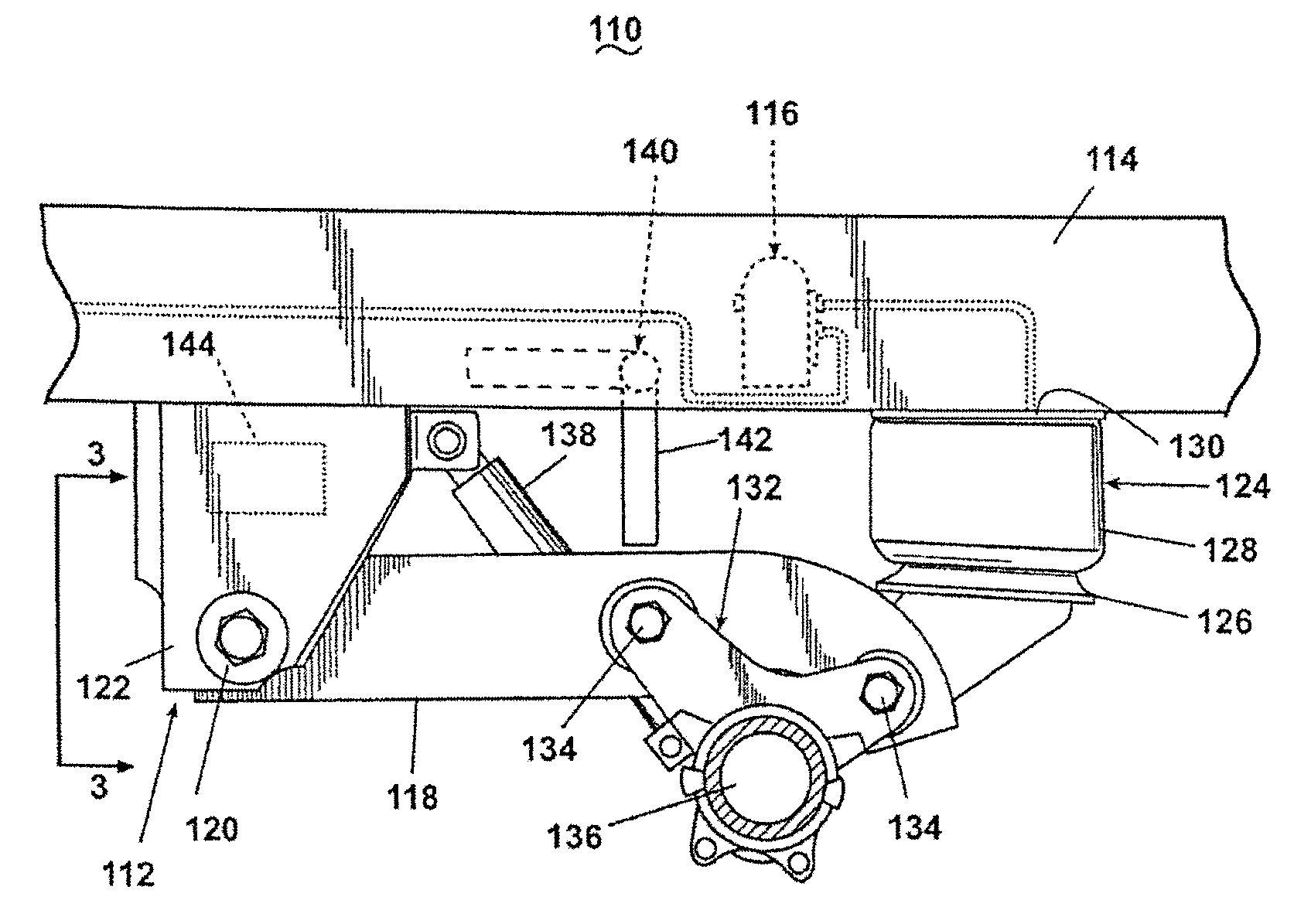
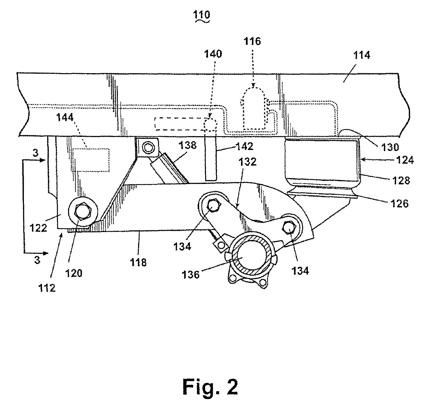
[0108]FIG. 21 illustrates a sixth embodiment height sensor 840 according to the invention. The height sensor 840 is similar to the height sensor 740 in that it uses a flexible variable resistor 744 which is wrapped about the coils of a helical or coil spring 842. The coil spring 842 is disposed within the interior of the shock absorber 138.

[0109]The shock absorber comprises an exterior cover 844 that is moveably mounted, to and overlies a cylinder 846 from which extends a piston shaft 848, which also extends through the cover 844. The coil spring 842 is wrapped around the piston shaft 848 and has one end attached to the cover 844 and another end attached to an upper portion of the cylinder 846.

[0110]The height sensor 840 functions substantially identically to the height sensor 740 in that as the trailing arm 118 rotates relative to the vehicle frame 114, the shock absorber cover 844 reciprocates relative to the housing 846 to compress or expand the coil spring 842, which bends the f...


PUM


Abstract

A control system for controlling the ride height of a vehicle, the system including a controller that receives and processes multiple variable inputs to provide enhanced ride height control. The inputs include a brake system signal including an Automatic Braking System (ABS) signal and/or an Electronic Braking System (EBS) signal, a remote setpoint signal and/or a fluid dump signal. The system also provides for measuring the actual ride height, filtering the measured ride height, determining if the filter ride height signal exceeds a threshold level, and adjusting the ride height accordingly.

Description

FIELD OF THE INVENTION[0001]The invention generally relates to a vehicle suspension system and specifically to an electronic height control system for controlling the ride height of the vehicle.BACKGROUND OF THE INVENTION[0002]Vehicle suspension systems with mechanically linked and actuated height control valves are well known. FIG. 1 illustrates such a trailing arm suspension 10 in combination with a height control valve 12. The trailing arm suspension 10 comprises opposing trailing arm assemblies 11 mounted on opposite sides of the vehicle, preferably to the vehicle frame rails 16. Each of the trailing arm assemblies includes a trailing arm 14 having one end pivotally connected to a hanger bracket 18 by a pivotal connection 20. The hanger bracket is suspended from the vehicle frame rail 16. The other end of the trailing arm 14 mounts to an air spring 22, which is affixed to the frame rail 16. The air spring 22 dampens the pivotal rotation of the trailing arm 14 about the hanger br...

Claims


Application Information

Patent Timeline
IPC IPC(8): B60G17/0195B60G17/015
CPCB60G9/003B60G11/27B60G17/019B60G2204/116B60G2200/31B60G2202/152B60G17/0525B60G11/26B60G17/00B60G17/018
Inventor PLATH, VICTOR A.
Owner HALDEX BRAKE
Why Eureka
Try Eureka