Motor drive circuit and method

a technology of motor drive and motor stop, which is applied in the direction of motor/generator/converter stopper, electronic commutator, dynamo-electric converter control, etc., can solve the problems of rotation irregularity, inability to detect the zero-cross point during the off time,

Inactive Publication Date: 2008-10-16
ROHM CO LTD
View PDF1 Cites 57 Cited by
  • Summary
  • Abstract
  • Description
  • Claims
  • Application Information

AI Technical Summary

Benefits of technology

[0012]The present invention has been made in light of this situation, and a general purpose thereof is to provide motor drive technology in which detection of a zero-cross point is possible even during OFF time.

Problems solved by technology

ected. Therefore, conventionally it has been possible to perform detection of a zero-cross point only during the ON time-period Ton, but there has been a problem in that detection of the zero-cross point could not be performed during the OFF time-perio
On the other hand, in cases in which the zero-cross point is taken to occur during the OFF time-period Toff, since voltage comparison cannot be performed at that point in time, it has been necessary to wait for the next ON time-period Ton, in order to actually detect the zero-cross point, a time lag τ occurs, causing rotational irregularity or the like.

Method used


Image

  • Motor drive circuit and method
  • Motor drive circuit and method
  • Motor drive circuit and method

Examples


Embodiment Construction

[0049]The invention will now be described based on preferred embodiments which do not intend to limit the scope of the present invention but exemplify the invention. All of the features and the combinations thereof described in the embodiment are not necessarily essential to the invention.

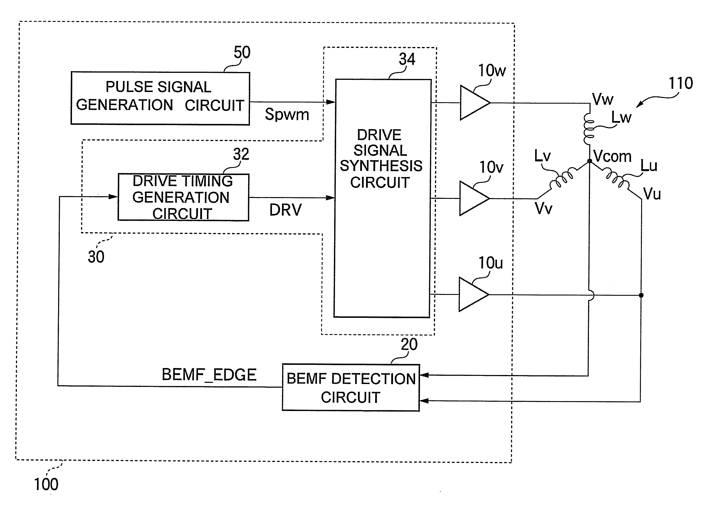
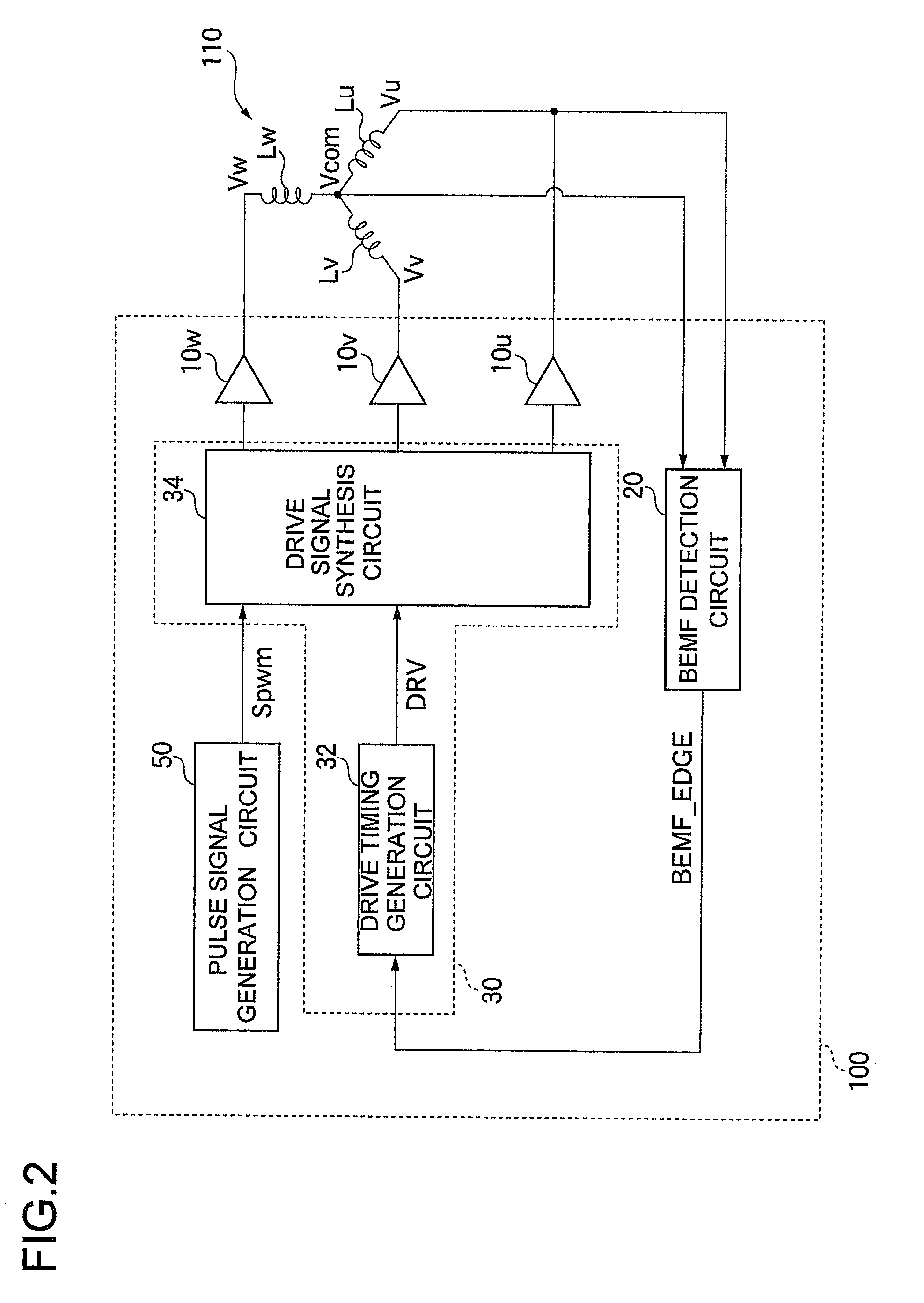
[0050]FIG. 2 is a block diagram showing a configuration of a motor drive circuit 100 according to an embodiment. The motor drive circuit 100 supplies a drive current to a sensorless, brushless DC motor (simply referred to below as a motor 110), to control rotation. In the present embodiment, the motor 110, which is to be driven, is a three phase DC motor including coils Lu, Lv, and Lw, of phase U, phase V, and phase W.

[0051]The motor drive circuit 100 is provided with switching circuits 10u, 10v, and 10w (referred to collectively as switching circuits 10), a BEMF detection circuit 20, a switching control circuit 30, and a pulse signal generation circuit 50. The motor drive circuit 100 is integrated...


PUM


Abstract

A motor drive method which supplies a drive current in a pulse form to a multiphase motor, to drive the motor. The motor drive method includes the steps of: generating a pulse signal having a duty ratio in accordance with torque, alternately repeating an ON time-period and an OFF time-period in accordance with the pulse signal, to supply a drive current in a pulse form to a phase coil currently driving, interpolating back electromotive voltage of the OFF time-period (Toff), using a back electromotive voltage (Vu) of the ON time-period (Ton), with respect to the back electromotive voltage (Vu) occurring in at least one coil of the multiphase motor, to generate an interpolated virtual back electromotive voltage (Vu′), detecting a zero-cross point, by comparing the interpolated virtual back electromotive voltage (Vu′) with a midpoint voltage (Vcom) of the coil, to generate a BEMF detection signal (BEMF_EDGE), and switching a phase to be driven, based on the BEMF signal (BEMF_EDGE).

Description

BACKGROUND OF THE INVENTION[0001]1. Field of the Invention[0002]The present invention relates to technology for controlling rotation of a rotor, and in particular, to a motor drive circuit which controls rotation of a motor including a stator having a plurality of coils and a rotor that is magnetic.[0003]2. Description of the Related Art[0004]A brushless direct-current motor is used for rotating a disk in electronic devices using disk-type media, such as portable CD (Compact Disc) devices, DVD (Digital Versatile Disc) devices, and the like. In general, the brushless direct-current (DC) motor is provided with a rotor having a permanent magnet, and a stator having a plurality of phase coils connected in a star configuration; the coils are excited by controlling current supplied to the coils, and the rotor is driven by rotation relative to the stator. The brushless DC motor is generally provided with a sensor such as a Hall element, optical encoder, or the like, in order to detect rota...

Claims


Application Information

Patent Timeline
Patent Type & Authority Applications(United States)
IPC IPC(8): H02P6/18H02P6/06H02P6/08H02P6/182
CPCH02P6/08H02P6/142H02P6/15H02P6/182
Inventor SUGIE, HISASHI
Owner ROHM CO LTD
Why Eureka
Try Eureka