Continuous-time digital controller for high-frequency dc-dc converters

a digital controller and converter technology, applied in the direction of transmission systems, electric variable regulation, instruments, etc., can solve the problems of compromising voltage regulation, limited use, and inability to directly apply hysteretic control

Inactive Publication Date: 2008-10-16
PRODIC ALEKSANDAR +1
View PDF4 Cites 70 Cited by
  • Summary
  • Abstract
  • Description
  • Claims
  • Application Information

AI Technical Summary

Problems solved by technology

Still, in the targeted systems their use is often limited.
There are several reasons for this limited use such as, for example, the voltage mode hysteretic control cannot directly be applied for boost converters [25], while in buck topologies it can compromise voltage regulation.
Current mode hysteretic controllers can eliminate the previously mentioned problems but their practical realization is challenging.
Similar to switching surface [7]-[10] and trajectory path [22]-[23] methods, these controllers often require measurement of the output capacitor current and / or a costly high gain-bandwidth current amplifying circuit.
Since the complexity of these systems significantly exceeds that of a complete conventional PWM controller [1], they have not been widely adopted in high-frequency low-power SMPS.
No attempt has been made to create a practical system capable of operating over a wide operating range.
This may be due to the requirement for a relatively complex calculation to achieve an optimal switching sequence, including on and off transistor times, which cannot be easily realized with analog hardware.
In this solution the fast transient response comes at the price of fairly complex controller hardware.
The practical realization of this solution can be costly.
However, due to the sampling effect and inherent delays of digital systems, at the very best, the digital PWM controllers have dynamic characteristics slower than their analog counterparts.
The slower response of the digital systems results in significantly larger and more expensive power stage components, which in most cases completely nullify all of the abovementioned advantages of digital control.

Method used


Image

  • Continuous-time digital controller for high-frequency dc-dc converters
  • Continuous-time digital controller for high-frequency dc-dc converters
  • Continuous-time digital controller for high-frequency dc-dc converters

Examples


example

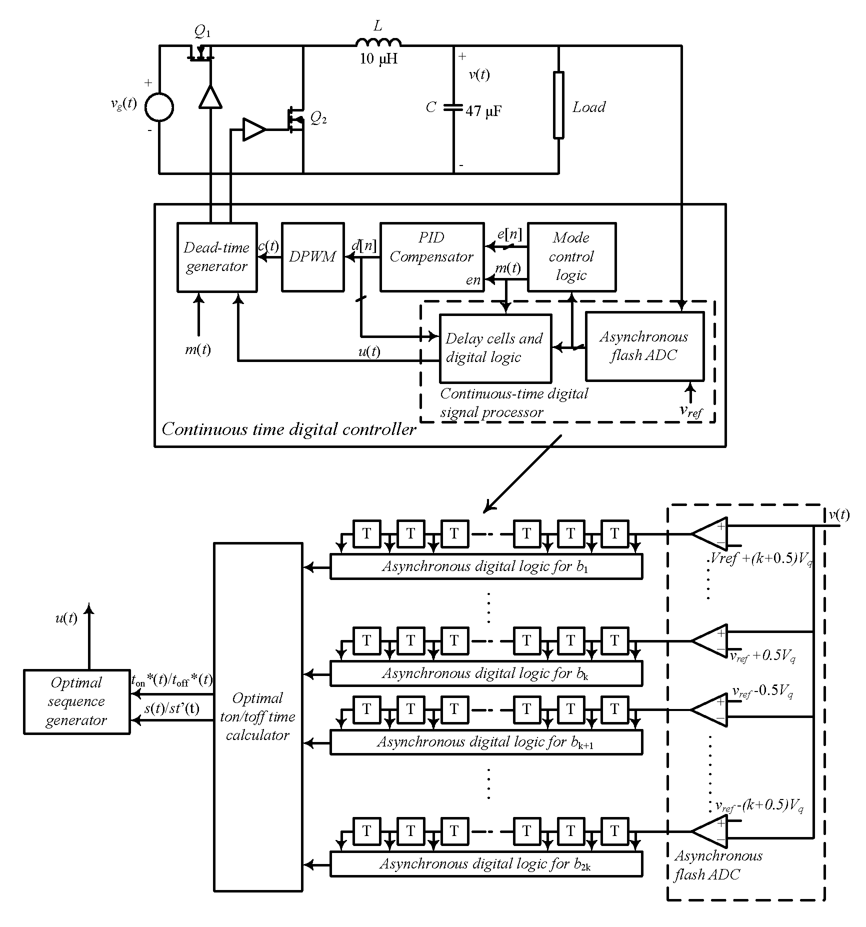
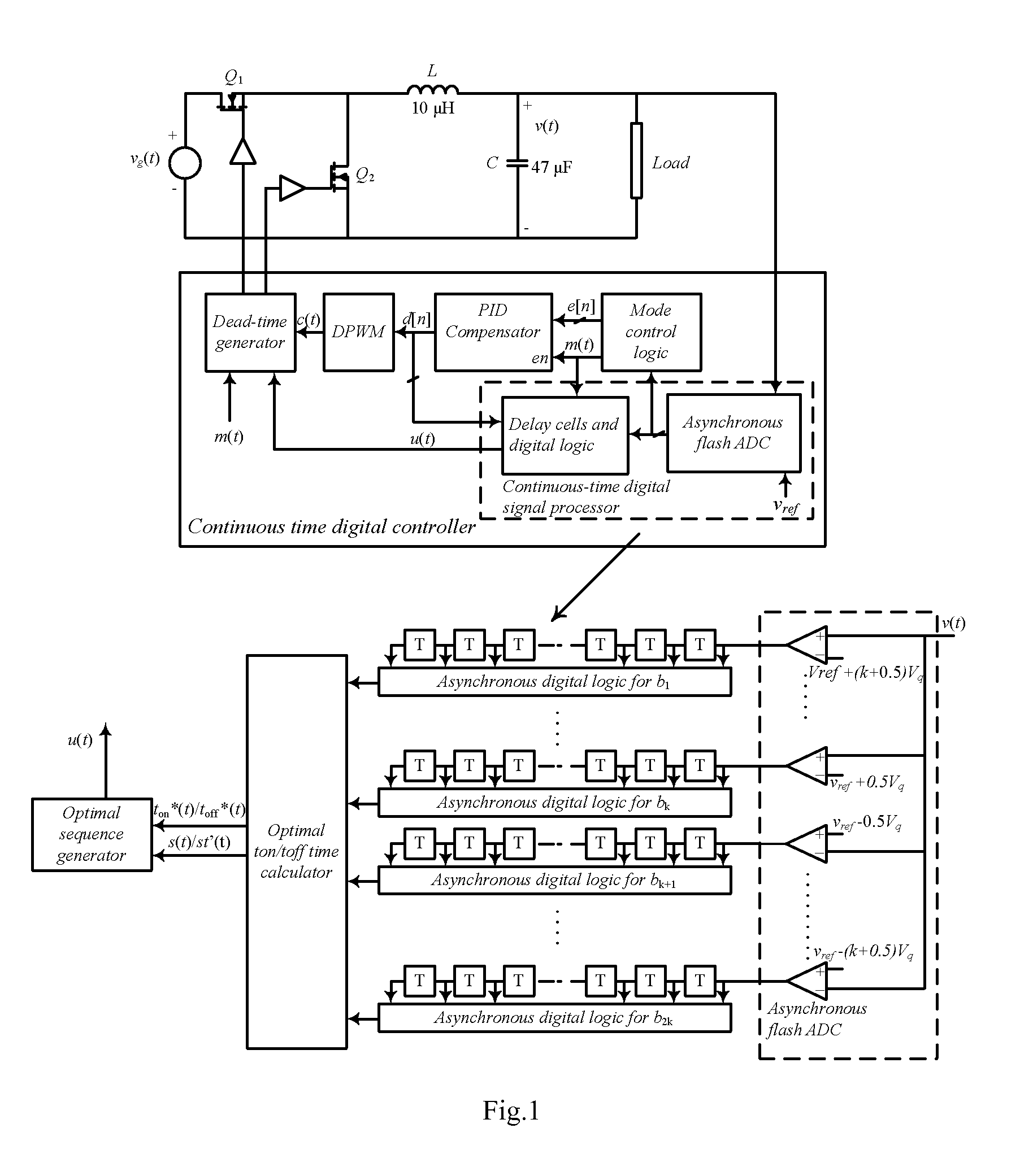
[0081]As an example, a continuous-time digital controller was implemented with an FPGA based system as well as with commercially available comparators and programmable delay lines. To design an asynchronous flash ADC, only 8 comparators were used and a constant quantization step of Vq=25 mV was set. The delay lines were comprised of 64 cells, each having 40 ns propagation time, to provide sufficiently long total delay to capture a time intervals between two successive triggerings of CT-DSP's comparators which is usually shorter than the switching period.

[0082]It should be noted that in on-chip implementation, where it is desired to minimize silicon area, the number of cells can be significantly reduced by sharing only one delay line among all comparators and using current-starved delay elements. The propagation time of the current starved cells can be shorter than 1 ns, allowing the use of the continuous-time digital controller in SMPS operating at switching frequencies of several M...


PUM


Abstract

The present invention is a voltage mode digital controller for low-power high-frequency dc-dc converters that has recovery time approaching physical limitations of a given power stage. It consists of a digital controller with load transient response approaching physical limitations of a given power stage that is suitable for low-power SMPS. In one aspect the invention is a method of utilizing a continuous-time digital signal processor (CT-DSP) for regulation of the operation of switch-mode power supplies. A CT-DSP can be used to instantaneously detect changes of voltage or current during transition periods and immediately perform control action that results in the fastest possible response. The invention may include current program mode controllers for SMPS where the input current is sensed as well as power factor correction rectifiers (PFC), where often input voltage, input current and output voltage are sensed. Upon sensing a deviation in the input voltage the CT-DSP is utilized to apply a switch-mode power operation whereby the controller switches between continuous-time and digital function.

Description

[0001]This application claims the benefit of U.S. Provisional Patent Application No. 60 / 910,839, filed Apr. 10, 2007.FIELD OF THE INVENTION[0002]The present invention relates in general to the regulation of dc-dc switched-mode power supplies. The present invention also relates in general to the field of digital and mixed signal controllers.BACKGROUND OF THE INVENTION[0003]Reference to background documents refers to the “List of References” provided below.[0004]Fast response to load transients and other disturbances as well as tight output voltage regulation are among the most important requirements in modern low-power dc-dc switch-mode power supplies (SMPS)[1], processing power that may range from a fraction of watt to several hundreds of watts. Few of many advantages of the fast transient response are listed here. In cost-sensitive point-of-load (POL) applications and portable systems, improvements in the load transient response usually result in a substantial reduction of the size...

Claims


Application Information

Patent Timeline
Patent Type & Authority Applications(United States)
IPC IPC(8): G05F1/10
CPCH02M3/157H03K7/08
Inventor PRODIC, ALEKSANDARZHAO, ZHENYU
Owner PRODIC ALEKSANDAR
Why Eureka
Try Eureka