Multi-resonant broadband antenna

a broadband antenna and multi-resonant technology, applied in the direction of antennas, antenna details, antenna earthings, etc., can solve the problems of affecting the performance the radiation efficiency of the small multi-band antenna abruptly deteriorates, and the multi-band antenna may not be suitable for multi-band use, so as to improve the return loss and enhance the performance characteristics

Active Publication Date: 2008-10-16
HANWHA SYST CO LTD
View PDF9 Cites 34 Cited by
  • Summary
  • Abstract
  • Description
  • Claims
  • Application Information

AI Technical Summary

Benefits of technology

[0012]It is yet another object to provide a small multi-band antenna producing three or more resonances with enhanced performance characteristic

Problems solved by technology

Accordingly, the PIFA may not be suitable to be used as a multi-band antenna producing three or more resonances.
If such a small multi-band antenna is realized to show multi-resonant characteristics however, radiation efficiency of the small multi-band antenna abruptly deteriorates.
Thus, if the small multi-band antenna is used as a multi-resonant antenna producing three or more resonances, a problem may occur in

Method used


Image

  • Multi-resonant broadband antenna
  • Multi-resonant broadband antenna
  • Multi-resonant broadband antenna

Examples


Embodiment Construction

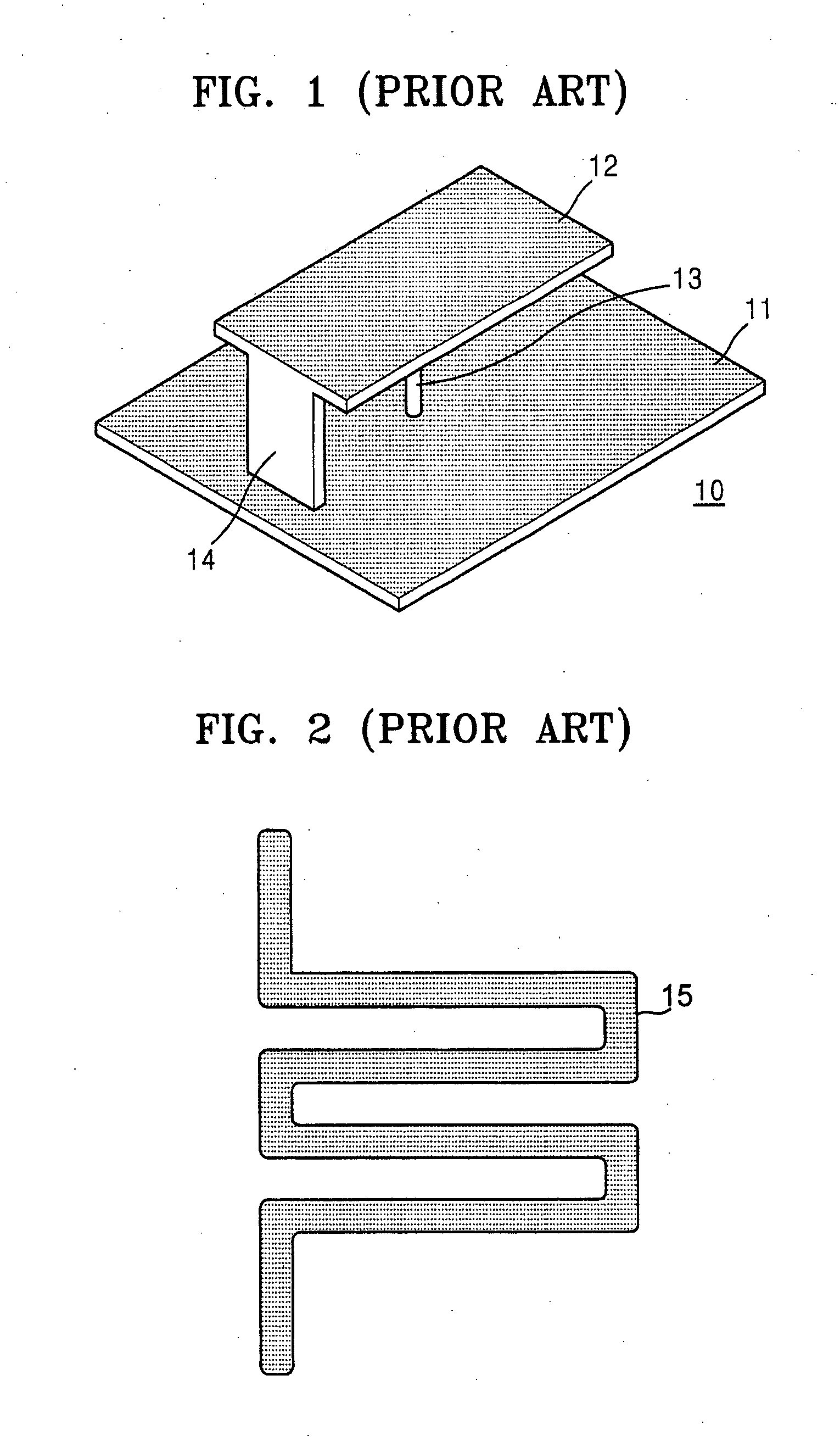
[0035]Turning now to the drawings, examples of a currently used multi-band antenna include a planner inverted F antenna (PIFA) illustrated in FIG. 1, an antenna having a meander line structure illustrated in FIG. 2, a stack type patch antenna, etc.

[0036]A structure of a contemporary PIFA 10 illustrated by FIG. 1, is constituted in an inverted F shape on ground plane 11 and divided into feed line 13 and short-circuit 14. The short-circuiting part 14 short-circuits radiation element 12 of the PIFA 10 from ground plane 11 and shows a resonance characteristic which has a dependence on a distance of separation between feed line 13 and short-circuit 14 and on the shapes of feed line 13 and short-circuit 14. In order to realize a multi-resonant characteristic in PIFA 10, radiation element 12 above PIFA 10 is divided into portions having different sizes and then combined. In other words, several antennas having single band characteristics are combined and used. PIFA 10 may be realized as a ...


PUM


Abstract

A multi-resonant broadband antenna constructed with a dielectric substrate; a fractal radiation element having a predetermined fractal grid structure adhered on an upper surface of the dielectric substrate. A feed line adhered on the upper surface of the dielectric substrate feeds the fractal radiation element, and a ground plane positioned on a lower surface of the dielectric substrate opposite to the feed line, is physically separated by the dielectric substrate from the feed line.

Description

CLAIM OF PRIORITY[0001]This application makes reference to, incorporates the same herein, and claims all benefits accruing under 35 U.S.C.§119 from applications for MULTI-RESONANT BROADBAND ANTENNA earlier filed in the Korean Intellectual Property Office on the 16 Apr. 2007 and there duly assigned Serial No. 10-2007-0037160, filed on the 30 May 2007 and duly assigned Serial No. 10-2007-0052930, and filed on the 30 May 2007 and duly assigned Serial No. 10-2007-0052929.BACKGROUND OF THE INVENTION[0002]1. Field of the Invention[0003]The present invention relates to a multi-resonant broadband antenna for use in a multiple frequency band, and more particularly, to a multi-resonant broadband antenna having a fractal structure.[0004]2. Description of the Related Art[0005]Examples of a currently used multi-band antenna include a planner inverted F antenna (PIFA) which has an antenna with a meander line structure or a stack type patch antenna employed as the radiation element. The convention...

Claims


Application Information

Patent Timeline
IPC IPC(8): H01Q1/38H01Q5/10H01Q5/15
CPCH01Q1/2208H01Q1/38H01Q5/385H01Q15/0093H01Q5/371H01Q19/005H01Q15/0006
Inventor BAE, KI-HYOUNGKIM, KUN-WOOTAE, HYUN-SIK
Owner HANWHA SYST CO LTD
Why Eureka
Try Eureka