Medical device for treating a heart valve insufficiency or stenosis

a heart valve and insufficiency technology, applied in the field of medical devices for treating insufficiency or stenosis of heart valves, can solve the problems of inability to close, patient at considerable risk, narrowing (stenosis), etc., and achieve the effect of minimising the risk of tissue damage and the implantation process

Active Publication Date: 2008-10-16
JENAVALVE TECH INC
View PDF112 Cites 500 Cited by
  • Summary
  • Abstract
  • Description
  • Claims
  • Application Information

AI Technical Summary

Benefits of technology

[0057]In one, particularly preferred embodiment of the medical device, the device comprises an endoprosthesis (stent) and a heart valve prosthesis, preferably a bio-heart valve prosthesis, even more preferably an aortic heart valve prosthesis. The valve is attached to the anchoring segment of the endoprosthesis by means of a thread, suture or similar. Orifices are provided in the retaining arches of the endoprosthesis through which the thread or similar is inserted. It would be conceivable for the heart valve prosthesis to be connected to the anchoring segment of the endoprosthesis immediately prior to the medical intervention. As a result, the medical device can be made in a modular design, which is of particular advantage in terms of transporting and storing the device. A bio-heart valve prosthesis may comprise material from a variety of sources such as from human, bovine, equine or porcine tissue. Bio-heart valves may be naturally occurring valves or they may be artificially derived or manufactured from suitable biological material, cells or tissue. Alternatively a heart valve prosthesis may be manufactured from biologically compatible artificial materials, that is non-biological sources such as, for example, from pyrolytic carbon, titanium, Teflon, polyester, Dacron and the like.
[0058]As regards the preferred material used for the endoprosthesis of the medical device, a shape memory material is ideally used which is designed so that the endoprosthesis is transformed from one shape to another shape by means of an external stimulus. Thus, the endoprosthesis assumes a minimised shape in the first mode (when the medical device is in the minimised state) and an open shape in the second mode (when the medical device is in the expanded state). Especially if a shape memory material such as Nitinol is used, i.e. an equal atomic alloy of nickel and titanium, the implantation process will be particularly gentle during the operation of implanting the medical device, minimising the risk of tissue damage on insertion and implantation. Another advantage of using a shape memory metal is that the open shape can be transformed back to the minimised shape simply by reversing the external stimulus.
[0059]During production of an endoprosthesis made from a shape memory material, after the stent structure has been cut from the metal tube, it is deformed and fixed in the desired open shape via a process known as “programming”. This operation may be performed on the one hand by heating, deforming and then cooling the stent structure. Alternatively, the stent structure may also be deformed at low temperature by an operation known as cold stretching. As a result, the open shape is memorised whilst the minimised shape actually prevails. If the stent structure is then subjected to an external stimulus, the shape memory effect is triggered and the memorised open shape is restored.
[0060]In a particularly preferred embodiment, the external stimulus is a settable switching temperature. It is therefore conceivable for the endoprosthesis material to be heated to a temperature higher than the switching temperature in order to trigger the shape memory effect and thus restore the memorised open shape of the endoprosthesis. By selecting an appropriate chemical composition of the shape memory material, a specific switching temperature can be fixed before the endoprosthesis is programmed. This being the case, the switching temperature is set so that it falls within the range of room temperature and the body temperature of the patient. This is of particular advantage in applications where the medical device is to be implanted in a patient's body. Accordingly, when implanting the medical device, it is merely necessary to ensure that the instrument is not heated until it is in the implanted state on the patient's body (36° C.), at which point the shape memory effect of the endoprosthesis material is triggered.

Problems solved by technology

The functional defect can result in narrowing (stenosis), inability to close (insufficiency) or a combination of the two (combined vitium).
This is a risky surgical intervention which places the patient at considerable risk and involves a long post-operative phase of treatment.
In multi-morbid patients in particular, the risk of carrying out such intervention is rarely justifiable.
With the known solutions there is still a risk of heart valves being incorrectly implanted.
Amongst other things, incorrect or sub-optimal implantation and positioning of a heart valve prosthesis can lead to inadequate sealing or valve insufficiency which places considerable stress on the ventricle.
For example, if a heart valve prosthesis is implanted too far above the actual heart valve plane, this can reduce or even cover and block the outlets of the coronary vessels (coronaries) leading to fatal coronary ischaemia due to heart infarction.
It is often not possible to obtain the required positioning accuracy due to restricted ability to manoeuvre, and in particular to ensure correct longitudinal positioning, of the heart valve prosthesis to be implanted with the fixing elements attached to it.
If there is a risk that the coronary vessels might close, implanting the heart valve prosthesis in a position angularly offset from the optimum implantation site represents a particular risk for the patient.
Known devices used for the transvascular implantation of heart valve prostheses are often not suitable for easy implantation of a heart valve prosthesis due to the required degree of positioning accuracy.
Furthermore, until now it has only been possible to correct an incorrectly positioned heart valve prosthesis that has already been partially implanted with great difficulty—if at all.

Method used


Image

  • Medical device for treating a heart valve insufficiency or stenosis
  • Medical device for treating a heart valve insufficiency or stenosis
  • Medical device for treating a heart valve insufficiency or stenosis

Examples


second embodiment

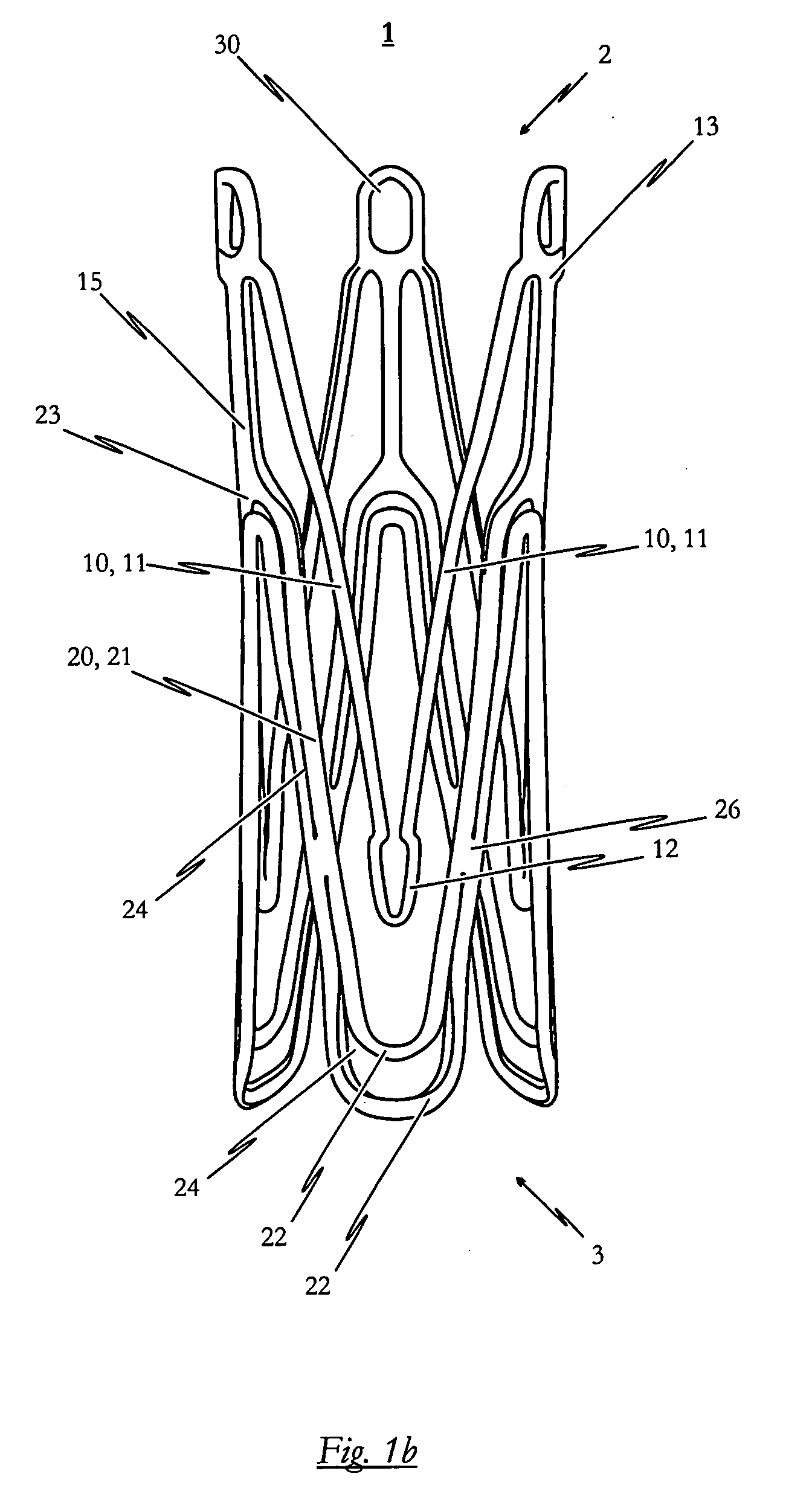
[0138]FIGS. 2a to 2c illustrate a self-expandable endoprosthesis 1 for the medical device proposed by the invention in its first, pre-definable mode (see FIG. 2a) in its second pre-definable mode (see FIG. 2c) as well as in a state in between (see FIG. 2b).

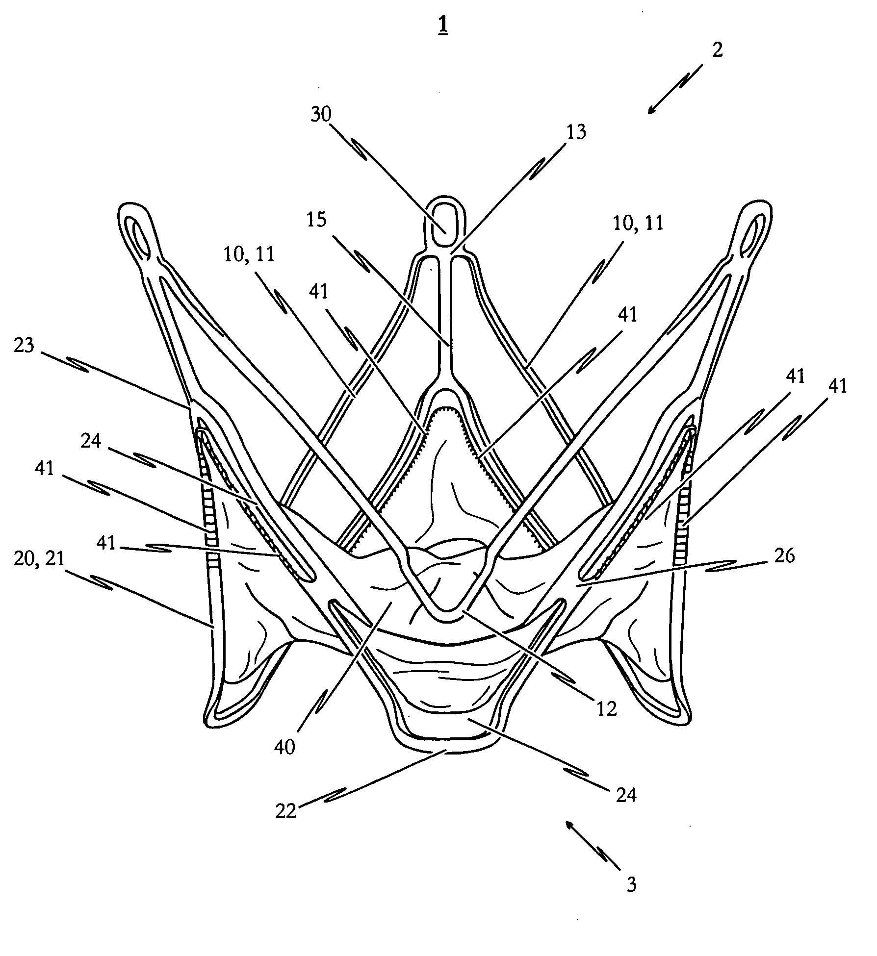
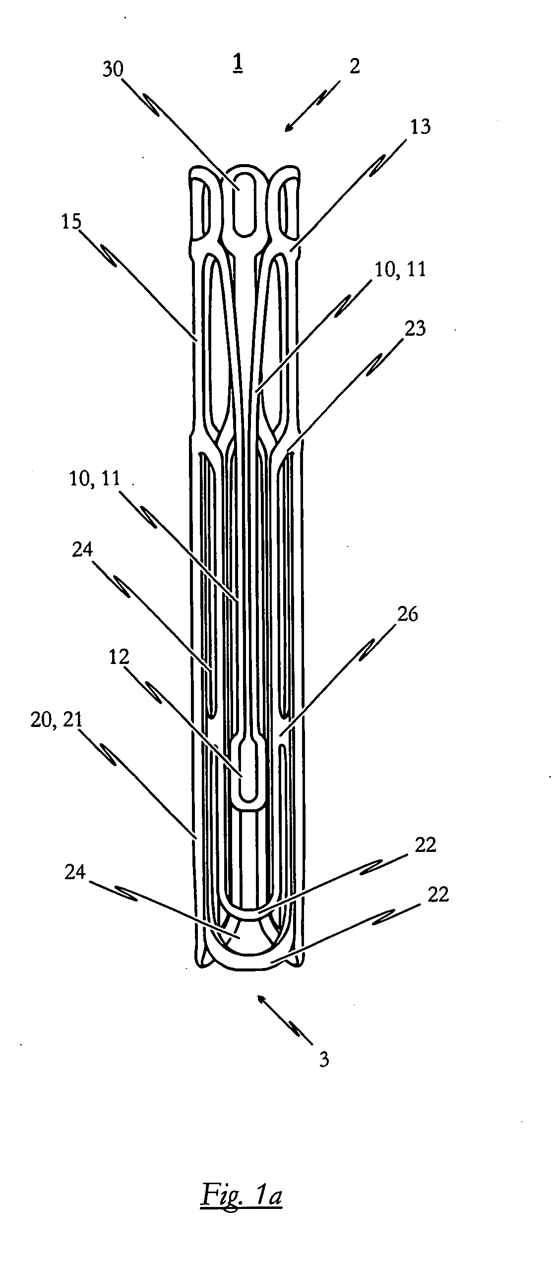
[0139]FIG. 2d illustrates a second embodiment of the medical device proposed by the invention in its expanded state with an endoprosthesis of the type illustrated in FIG. 2c and a heart valve prosthesis 40 attached to it and opened out. A flat projection of a cutting pattern which may be used for the production of the second embodiment of the self-expandable endoprosthesis is illustrated in FIG. 2e. This cutting pattern is suitable for cutting the endoprosthesis illustrated in FIG. 2a integrally from a metal tube.

[0140]The endoprosthesis 1 of the second embodiment essentially corresponds to the first embodiment described above with reference to FIGS. 1a to 1e. Description of the various components corresponds to that described for...

third embodiment

[0141]a self-expandable endoprosthesis for the medical device proposed by the invention illustrated in FIGS. 3a to 3c essentially corresponds to the first preferred embodiment illustrated in FIGS. 1a to 1c. The difference, however, is that in the third preferred embodiment, the retaining eyes 30 disposed between two adjacent positioning arches 10 are provided with barbs 17, the respective tips of which point in the direction of the proximal end 3 of the endoprosthesis 1. With this modification to the design additional anchoring is provided for the system to prevent the stent 1 from being dislocated in the direction of the left ventricle.

[0142]FIG. 3d illustrates a third embodiment of the medical device proposed by the invention in its expanded state with an endoprosthesis of the type illustrated in FIG. 3c and a heart valve prosthesis 40 attached to it and opened out. This diagram essentially corresponds to that of FIG. 1d. The difference, however, is that the barb elements 17 descr...

fifth embodiment

[0147]FIG. 5e illustrates a flat projection of a cutting pattern which may be used for production of the self-expandable endoprosthesis 1 to cut the endoprosthesis 1 illustrated in FIG. 5a integrally from a metal tube.

[0148]The sixth embodiment of the self-expandable endoprosthesis and the medical device proposed by the invention illustrated in FIGS. 6a to 6e corresponds to a combination of the second embodiment illustrated in FIGS. 2a to 2e and the fifth embodiment described above with reference to FIGS. 5a to 5e. Specifically, therefore, the endoprosthesis 1 based on the second embodiment is provided with additional reinforcing portions 26 at the respective retaining arches 21 which interrupt the slots 24 extending in the longitudinal direction of the retaining arches 21.

[0149]The seventh embodiment of the endoprosthesis 1 and the medical device proposed by the invention illustrated in FIGS. 7a to 7e corresponds to a combination of the third and fifth embodiments described above. ...


PUM


Abstract

A medical device for treating a heart valve insufficiency, with an endoprosthesis which can be introduced into a patient's body and expanded to secure a heart valve prosthesis in the patient's aorta with a catheter. In an embodiment, the endoprosthesis has a plurality of positioning arches configured to be positioned with respect to a patient's aorta and a plurality of retaining arches to support a heart valve prosthesis. The endoprosthesis includes a collapsed mode during the process of introducing it into the patient's body and an expanded mode when it is implanted. The endoprosthesis may be introduced into a patient's body and expanded via a catheter. In an embodiment, the catheter has first and second slide mechanisms configured to independently manipulate first and second sleeve elements to sequentially expand the endoprosthesis from the collapsed mode to the expanded mode.

Description

FIELD OF INVENTION[0001]This invention relates to a medical device for treating a heart valve insufficiency or stenosis. The medical device includes an endoprosthesis which can be introduced into a patient's body with minimal invasion and automatically expanded to position and secure a heart valve prosthesis in the patient's aorta.BACKGROUND OF INVENTION[0002]The expression “narrowing of a heart valve and / or heart valve insufficiency” is intended to include a functional defect of one or more heart valves which is either genetic or has developed over time due to age or disease. A valve defect of this type might affect each of the four coronary valves, although the valves in the left ventricle (aortal and mitral valves) are affected much more often than the right-hand part of the heart (pulmonary and tricuspid valves). The functional defect can result in narrowing (stenosis), inability to close (insufficiency) or a combination of the two (combined vitium).[0003]The operating principle...

Claims


Application Information

Patent Timeline
Patent Type & Authority Applications(United States)
IPC IPC(8): A61F2/24
CPCA61F2/2418A61F2002/9517A61F2/2436A61F2/9517A61F2/2427
Inventor STRAUBINGER, HELMUTJUNG, JOHANNES
Owner JENAVALVE TECH INC
Why Eureka
Try Eureka