Dynamic Adjustment of Wing Surfaces for Variable Camber

a technology of variable camber and wing surface, which is applied in the direction of process and machine control, instruments, navigation instruments, etc., can solve the problems achieve the effect of increasing the design burden on the actuation equipment, reducing airplane drag, and continual optimization of the lift-to-drag ratio

Active Publication Date: 2008-10-16
THE BOEING CO
View PDF8 Cites 30 Cited by
  • Summary
  • Abstract
  • Description
  • Claims
  • Application Information

AI Technical Summary

Benefits of technology

[0005]In a preferred implementation, the dynamic adjustment control module detects aircraft cruise conditions, and commands actuation of the optimum controlled surfaces to target positions for optimizing L / D ratios in such conditions. The control laws for actuating the commanded surfaces factor in the expected flight conditions over a period of time, since commanding changes that are not going to be maintained over an adequate duration is costly and increases the design burden on the actuation equipment based on fatigue and maintenance considerations. The calculated and dynamically controlled repositioning of some or all of the wing's trailing edge surfaces in the cruise state results in continual optimization of the lift-to-drag ratios for the wing. The more aerodynamically efficient wing camber adjustments can reap a benefit of as much as 2-5% reduction of airplane drag. Additional potential benefits include increased buffet margin and high lift span-load tuning for drag or wake-vortex roll-up control. The trailing-edge repositioning is automatic, so it requires no added pilot or ground crew work. It also facilitates the further development of adaptive wing control systems that can learn optimum control surfaces repositioning over time.

Problems solved by technology

The control laws for actuating the commanded surfaces factor in the expected flight conditions over a period of time, since commanding changes that are not going to be maintained over an adequate duration is costly and increases the design burden on the actuation equipment based on fatigue and maintenance considerations.

Method used


Image

  • Dynamic Adjustment of Wing Surfaces for Variable Camber
  • Dynamic Adjustment of Wing Surfaces for Variable Camber
  • Dynamic Adjustment of Wing Surfaces for Variable Camber

Examples


example implementation

of TEVC Control System

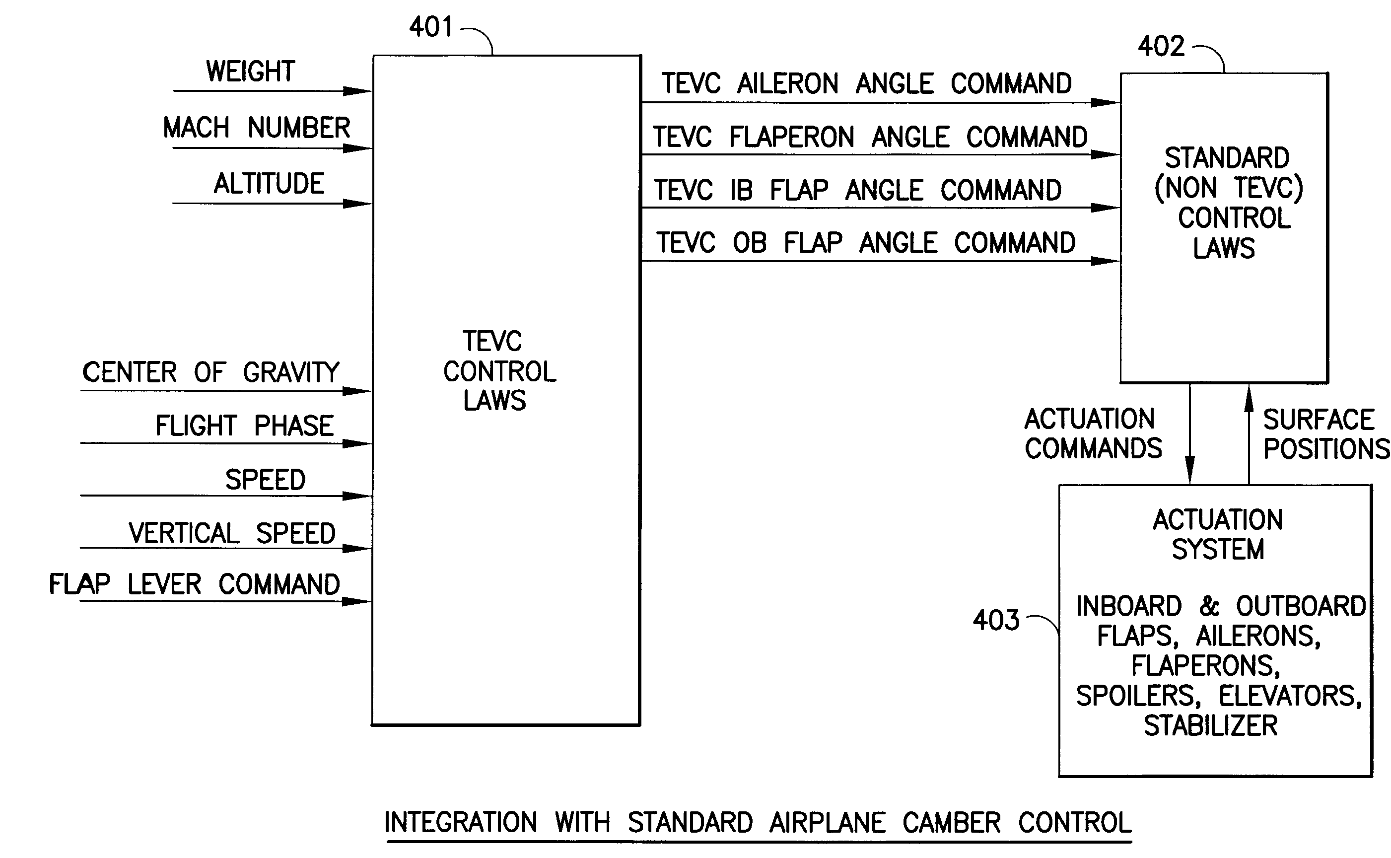
[0032]The particular approach to variable camber control for any aircraft is determined by the desired flying qualities of the airplane. The control system of the airplane is comprised of both the control laws and the actuation system, where the later is the means to achieve the control law computed deflection for the controlled surfaces. The general variable camber control approach for implementing a baseline TEVC function may follow these two high level concepts: (1) keep hardware and software changes to a minimum compared to an airplane baseline with no TEVC control designed in; and (2) provide a high lift flaps actuation system that allows for positioning of the Outboard (OB) flaps at different positions compared to the Inboard (IB) flaps. As a result, the design implementation for the purpose of accommodating TEVC control in the baseline is developed with certain operational characteristics. The TE flaps actuation system has a TEVC control unit on each win...


PUM


Abstract

The movable surfaces affecting the camber of a wing are dynamically adjusted to optimize wing camber for optimum lift / drag ratios under changing conditions during a given flight phase. In a preferred embodiment, an add-on dynamic adjustment control module provides command signals for optimum positioning of trailing edge movable surfaces, i.e., inboard flaps, outboard flaps, ailerons, and flaperons, which are used in place of the predetermined positions of the standard flight control system. The dynamic adjustment control module utilizes inputs of changing aircraft conditions such as altitude, Mach number, weight, center of gravity, vertical speed and flight phase. The dynamic adjustment control module's commands for repositioning the movable surfaces of the wing are transmitted through the standard flight control system to actuators for moving the flight control surfaces.

Description

TECHNICAL FIELD[0001]The invention described herein relates to a system for an optimized cruising control for aircraft, and particularly to an aircraft flight control system which dynamically adjusts a wing's movable surfaces for variable camber.BACKGROUND OF INVENTION[0002]The aircraft wing for commercial airplanes is designed such that the lift / drag (L / D) ratio is optimized for such conditions as cruising at particular speeds and altitudes. Operating at slightly different conditions from the optimum can mean increased fuel consumption. For military aircraft, optimizing L / D for (short) maneuvers could be more important than steady state L / D characteristics. U.S. Pat. No. 4,899,284 issued in 1990 to Lewis et al., entitled “Wing Lift / Drag Optimization System”, has provided for varying the wing camber such that L / D is optimized in flight but has focused on enhancement of the airplane L / D parameter for maneuvers. Other systems for wing camber control include U.S. Pat. No. 6,161,801 iss...

Claims


Application Information

Patent Timeline
Patent Type & Authority Applications(United States)
IPC IPC(8): G05D1/00B64C13/00
CPCB64C9/12Y02T50/32Y02T50/44Y02T50/30Y02T50/40
Inventor ONU, DANWINTER, JOHN D.CARR, CANDY L.VIJGEN, PAUL M.EMCH, GARY A.RENZELMANN, MICHAEL E.
Owner THE BOEING CO
Why Eureka
Try Eureka