High Rate Filtration System

a filtration system and high-rate technology, applied in water cleaning, water/sewage multi-stage treatment, separation processes, etc., can solve the problems of reducing the amount of room available for the media, complicating the operation of the device, and the difficulty of moving the bottom plate, so as to reduce the amount of media to be filtered, the effect of less media washing and low flow ra

Inactive Publication Date: 2008-10-23
SCHREIBER CORP
View PDF13 Cites 19 Cited by
  • Summary
  • Abstract
  • Description
  • Claims
  • Application Information

AI Technical Summary

Benefits of technology

[0015]The invention provides a high rate filtration system in which the collector size and effective pore size of the filtration media can be adjusted according to influent conditions and to promote efficient cleaning of the media. The fluid travels through successive layers of filter media in which each layer becomes progressively more compressed with a smaller effective pore size and collector size for filtration and removes smaller and smaller particles. The compression gradient promotes more uniform loading of the media throughout the filter bed. The compression gradient can be altered during filtration to adjust head loss across the media and to extend the time for filtration while maintaining filtration efficiency within acceptable limits.
[0021]There is no necessity to provide a seal in an upper movable plate for a ram or screw that is designed to move the lower movable plate. Channelling can be reduced and the filter bed is not interrupted. There is no mechanical means in which the media can become entangled.

Problems solved by technology

However, the apparatus described in the Masuda et al. patent with the movable bottom plate has some difficulties associated with it.
The screw decreases the amount of room available for the media and potentially causes some channeling through the media in the region of the screw.
A seal is used where the screw passes through the top plate, further complicating the operation of the device.
The filter clogs up fast because large particles and fines are both trapped by the compressed initial layers of the filter media.
However, the flow rate of the wash water makes it difficult to achieve separation between the media and to obtain efficient cleaning.
Thus the overall efficiency of the apparatus described in the Masuda patent is greatly reduced.

Method used


Image

  • High Rate Filtration System
  • High Rate Filtration System
  • High Rate Filtration System

Examples


Embodiment Construction

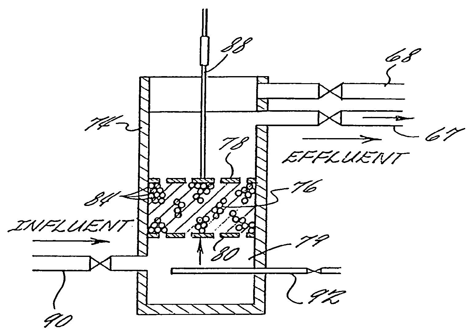
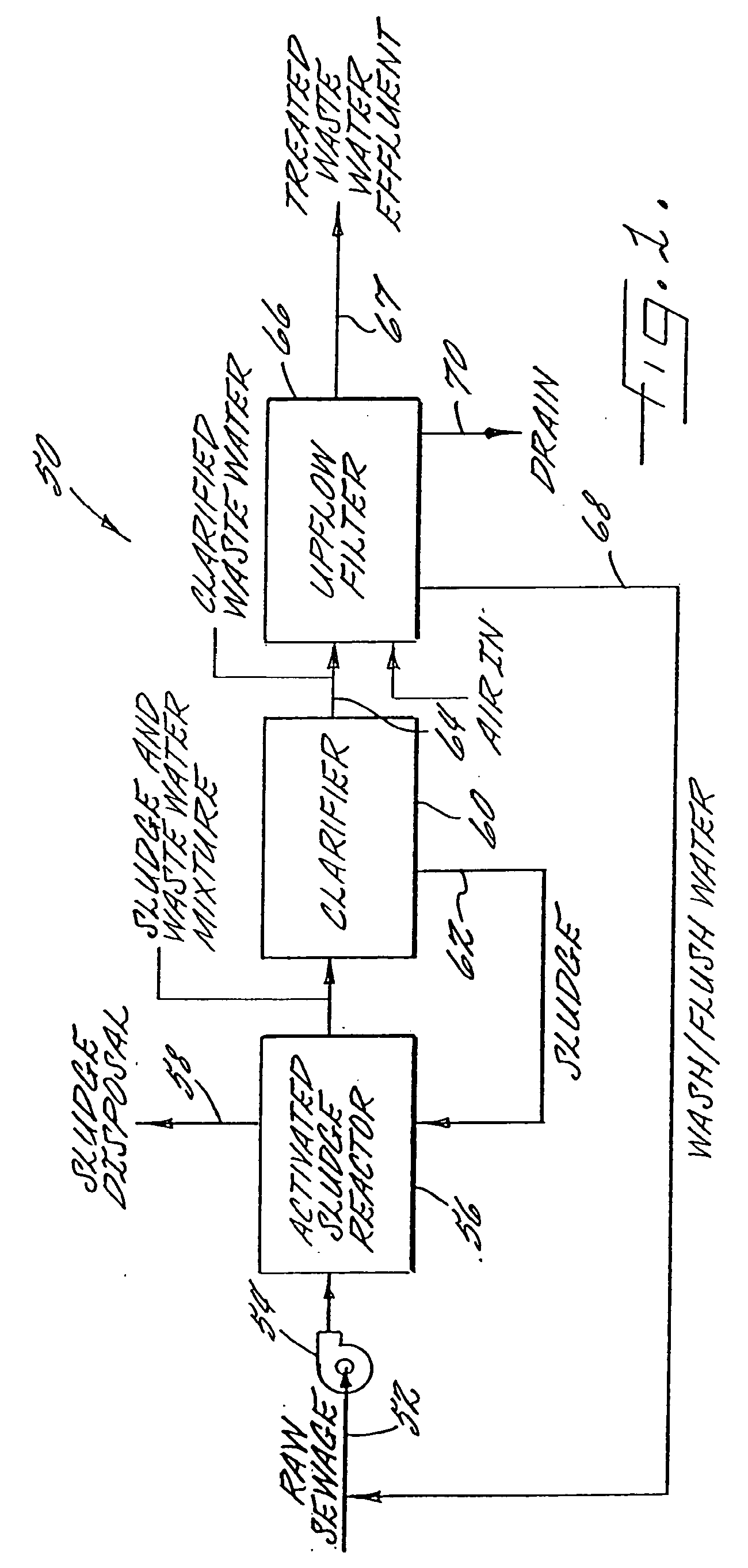
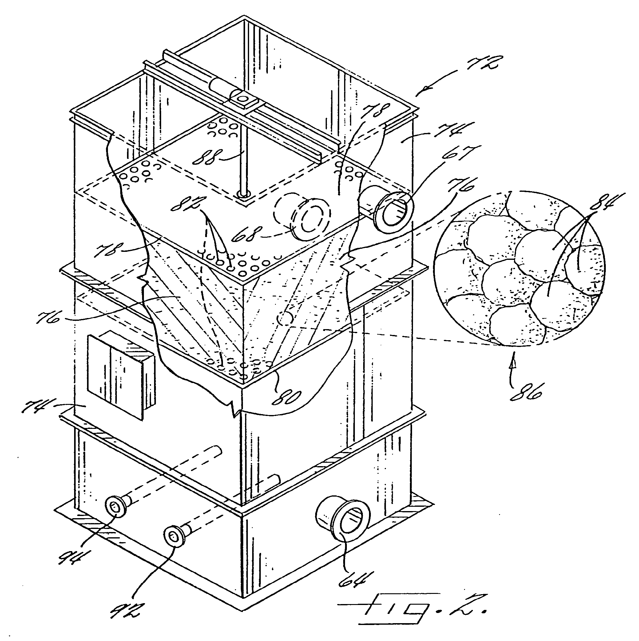
[0033]Represented in FIG. 1 generally at 50 in highly schematic form is a representative activated sludge plant incorporating the filtration apparatus of the invention for tertiary treatment of raw municipal sewage for increased removal of suspended solids. It should be recognized that the configuration of the activated sludge plant as represented is but one example of an activated sludge plant and that numerous alternatives are available. It should also be recognized that, while the invention is described in the context of a tertiary treatment system for municipal sewage that is treated by an activated sludge process, the invention described herein is not so limited.

[0034]The invention is not limited to particular configurations or modes of operation of activated sludge plants, or to use in connection with an activated sludge plant. For example, the filtration apparatus of the invention can be used to treat wastewater that is not subjected to sludge digestion. Where it is desired t...


PUM

PropertyMeasurementUnit
angleaaaaaaaaaa
porosityaaaaaaaaaa
porosityaaaaaaaaaa

Abstract

A high rate, upflow filtration system is described in which a compressible, fibrous lump filtration media is compressed to adjust the porosity and collector size of the media in the bed and to provide a porosity gradient within the bed proceeding from more porous to less porous in a direction opposite to the flow of fluid so that filtration proceeds in a direction from a more porous to a less porous filter bed. Larger particles are removed by the more porous media and successively smaller particles are removed as the filter bed becomes less porous. The system is capable of reducing the turbidity of influent municipal wastewater from about 8 NTU to about 2 NTU at a wastewater flow rate of from about 820 to 1230 L / m2·min (20 to 30 gal / ft2·min), at a bed compression ration of from about 15 to 40 percent, and at a backwash rate of from about 1 to 6 percent based on the total wastewater passing through the filter.

Description

CROSS REFERENCE TO RELATED APPLICATION[0001]This application is a continuation of copending U.S. application Ser. No. 10 / 661,349, filed Sep. 12, 2003, which is a continuation of U.S. application Ser. No. 10 / 098,738, filed Mar. 15, 2002, which is a continuation of U.S. application Ser. No. 09 / 627,638, filed Jul. 28, 2000, which is a continuation-in-part of U.S. patent application Ser. No. 08 / 980,537, filed Dec. 1, 1997, each of which is incorporated herein in its entirety and claims the benefit of U.S. Provisional Application No. 60 / 032,643, filed Dec. 10, 1996.FIELD OF THE INVENTION[0002]This invention relates to filtration systems, including filtration systems used in connection with tertiary treatment of wastewater for reduction of suspended solids.BACKGROUND OF THE INVENTION[0003]Disposal and reuse of wastewater from raw municipal sewage is problematic. Stringent wastewater treatment requirements have been promulgated to protect human health, particularly in those areas having li...

Claims


Application Information

Patent Timeline
Patent Type & Authority Applications(United States)
IPC IPC(8): B01D24/46C02F3/12B01D24/04C02F9/02B01D24/00
CPCB01D24/002B01D2201/186B01D24/04B01D24/4663B01D29/705
Inventor DEW, WILLIAM FREDERICK
Owner SCHREIBER CORP
Why Eureka
Try Eureka