
Battery discharge current sharing in a tightly regulated power system

a power system and discharge current technology, applied in the direction of electric vehicles, dc network circuit arrangements, transportation and packaging, etc., can solve the problems of long-term degradation or damage of batteries, ineffective utilization of battery capacity, and battery will give rise to a permanent short circuit, so as to inhibit battery charging and eliminate the risk of discharging one battery

Active Publication Date: 2008-10-23
THE BOEING CO
View PDF3 Cites 15 Cited by
  • Summary
  • Abstract
  • Description
  • Claims
  • Application Information

AI Technical Summary

Benefits of technology

[0008]Accordingly, it is an object of the present invention to provide a high power system having multiple batteries to provide back-up power when the primary power source is unavailable for protecting batteries against over-discharge and ensuring equal discharge current sharing for efficient battery capacity utilization.
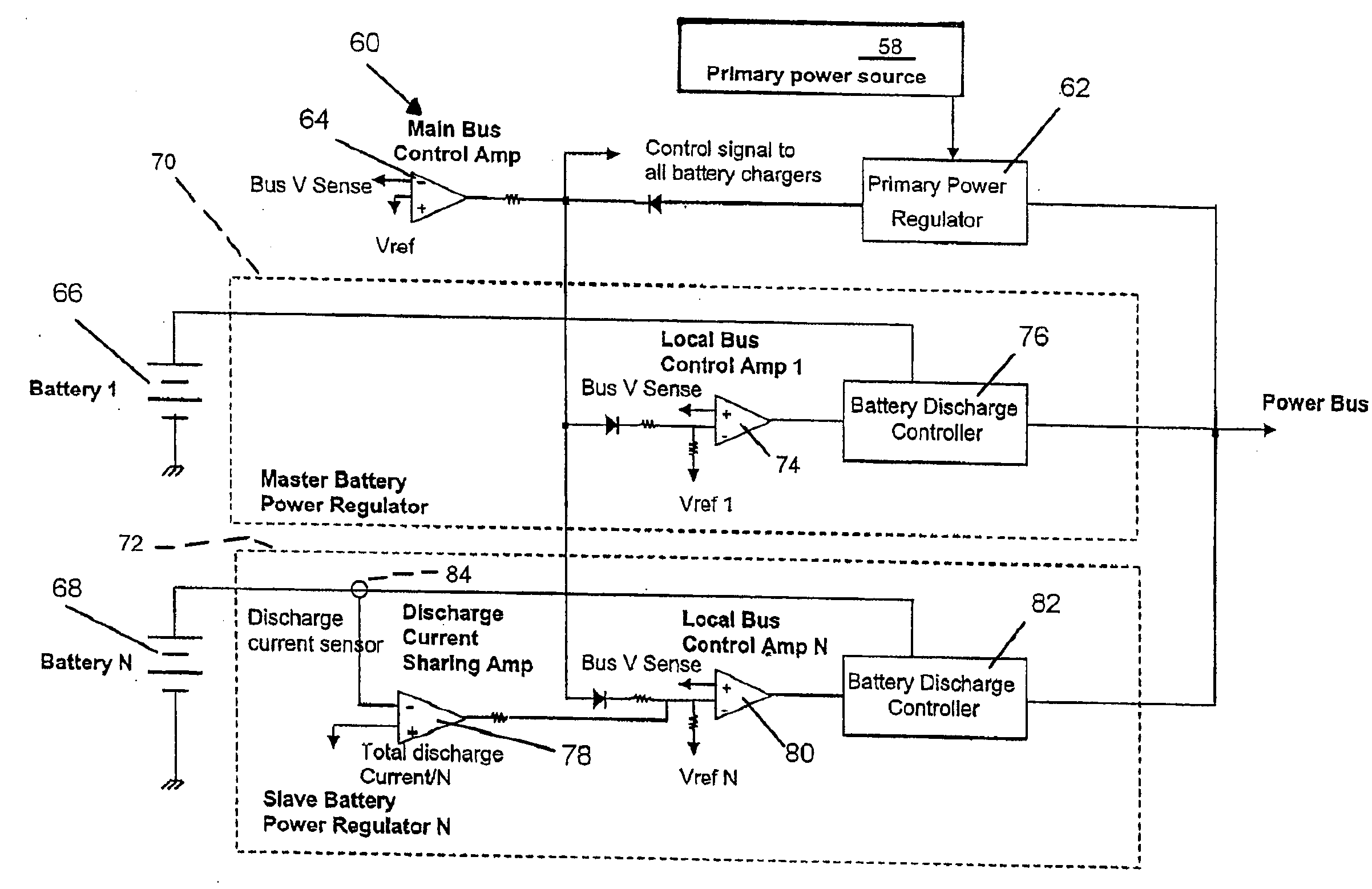
[0011]The present invention is intended for use in a regulated power system having a primary power source and plural batteries for providing back-up power, and contemplates an arrangement for tightly regulating primary power and back-up power and providing current sharing among the plural batteries. The arrangement comprises a main bus control amplifier for providing a control signal to both the primary power regulator and the battery discharge controllers for establishing a tightly regulated power bus voltage set-point. The primary power regulator has its own local bus control amplifier which is set at a higher bus voltage set-point. The local control amplifiers of the battery discharge controllers regulate at a lower bus voltage set-point. A negative control signal from the main bus control amplifier brings down the primary power regulator bus set-point to within a regulation range and activates all the battery chargers. A positive control signal raises up the battery discharge controller set-point to the same regulation range and inhibits battery charging. The power bus is thus tightly regulated. The single control amplifier eliminates the risk of discharging one battery to charge another battery. The current sharing amplifier in each slave battery power regulator, comparing its own discharge current to the average discharge current from all the batteries, outputs an error signal to modify the reference voltage in the slave local bus control amplifier. The local bus set-point in each slave unit thus varies to allow equal discharge current sharing from its associated battery.

Problems solved by technology

If discharge current sharing control is not implemented in a multiple battery power system, the consequences will likely result in the following undesirable conditions.
(1) Battery degradation or damage caused by over-discharging a battery which can lead to long term degradation or damage.
In the case of over-discharging a Lithium-ion battery, the battery will give rise to a permanent short circuit.
(2) Ineffective utilization of battery capacity involving the use of a scheme to terminate battery discharging in a nearly over-discharged battery by disabling its associated battery discharge power regulator.
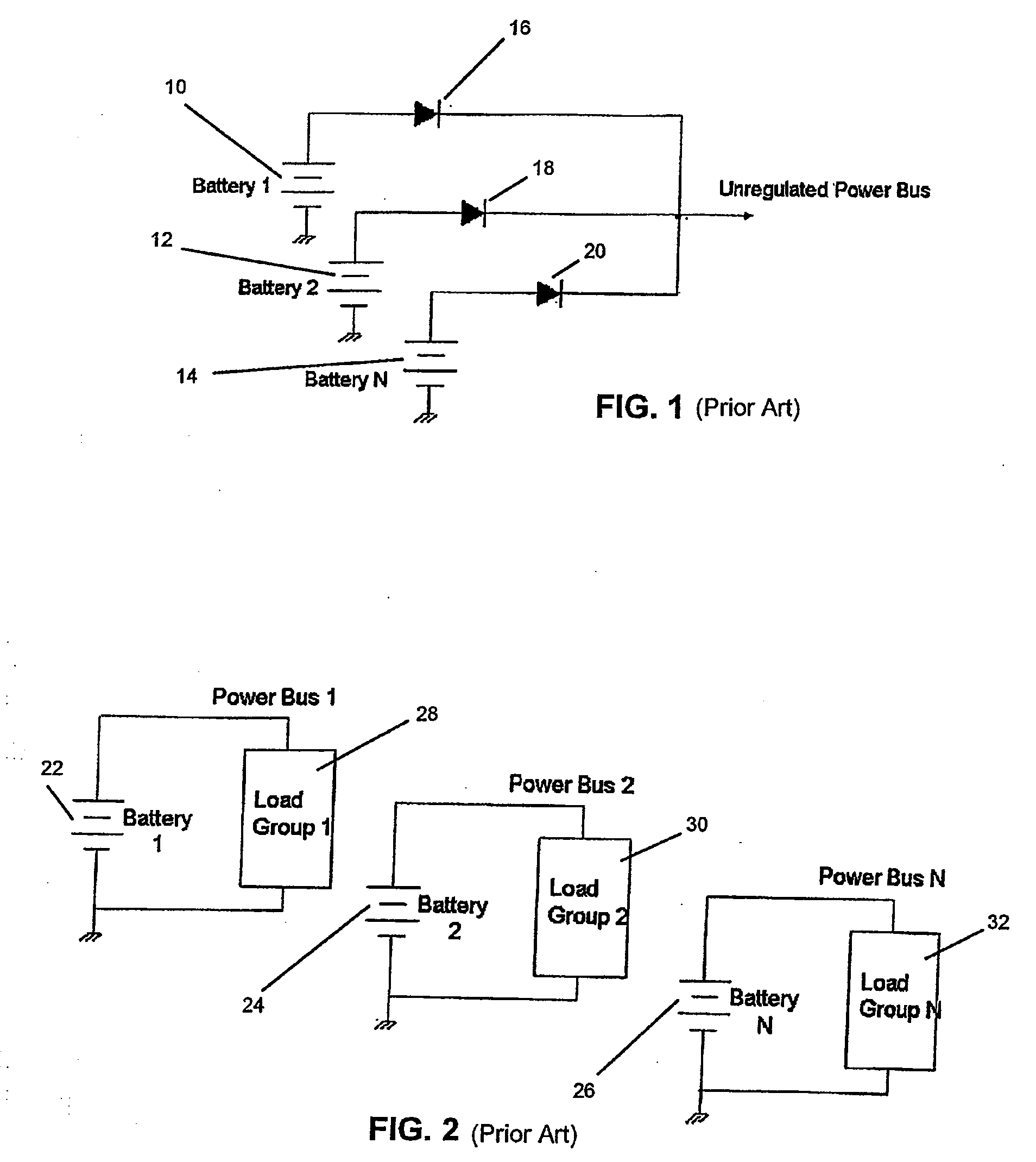
A disadvantage of this approach is that an unregulated power system places the burden on the load unit to operate over a wide range of bus voltages.
This type of power system typically results in higher mass and cost.
In addition, when all the batteries do not have the same number of battery cells due to cell failure and cell bypass, the capacity from the battery with lower cell count cannot be utilized to the full extent.
A disadvantage of this approach is that a system in which the loads are divided in load groups and powered by separate batteries typically results in a heavier system.
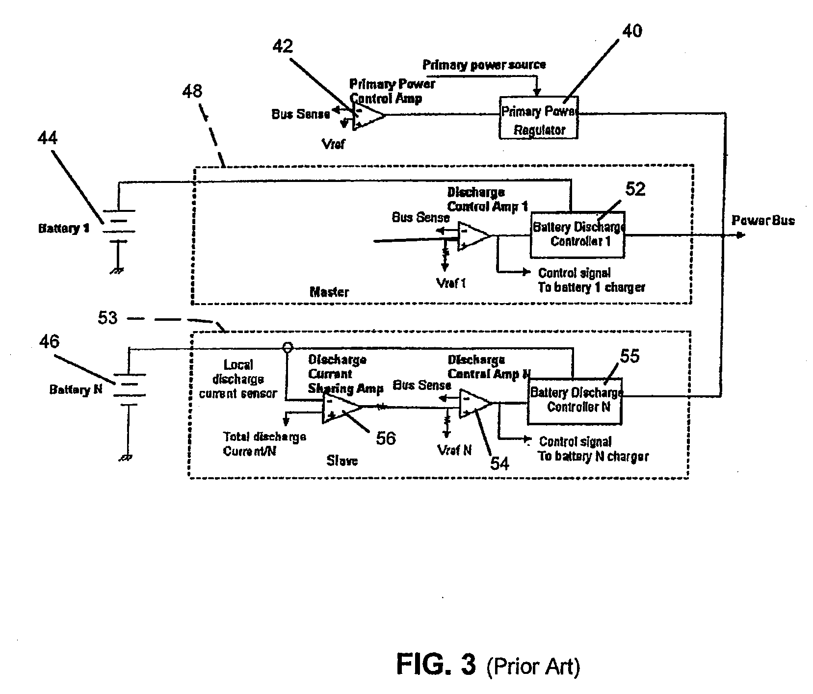
A disadvantage of this approach is that separate amplifiers controlling separate power regulators does not allow a very tightly regulated power bus.
If each power regulator has its own bus control amplifier and the bus set-points of these regulators are set too close to each other, it will introduce the risk of discharging one battery to charge another battery.

Method used


Image

  • Battery discharge current sharing in a tightly regulated power system
  • Battery discharge current sharing in a tightly regulated power system
  • Battery discharge current sharing in a tightly regulated power system

Examples


Embodiment Construction

[0017]Referring to FIG. 4, there is shown a tightly regulated power system 60 with battery discharge current sharing capability in accordance with the principles of the present invention. The tightly regulated power system 60 includes a primary power source 58 connected to a primary power regulator 62 for providing power to a power bus. The primary power source 58 may be virtually any type of arrangement for generating electric power which also operates with a battery back-up power system to provide power when the primary power source is unavailable. The inventive tightly regulated power system with battery discharge current sharing capability 60 is particularly adapted for use with a primary power source 58 comprised of a solar array such as used in a spacecraft where minimizing the mass of the power system is of critical importance and a battery back-up power capability is provided for the purpose of providing electric power during eclipse.

[0018]The tightly regulated power system ...


PUM


Abstract

In a high power system, plural batteries provide back-up power when primary power is unavailable. Each battery has an associated discharge controller which is controlled by a local bus control amplifier which regulates the power bus voltage set-point lower than the main bus voltage set-point. A single main bus control amplifier tightly regulates the power bus to a main bus voltage set-point and controls charging and discharging of all batteries to prevent charging of one battery at the expense (discharge) of another battery. There is one master battery discharge controller, with the remaining controllers being slave units. A local bus voltage set-point of each slave unit varies under the control of a slave unit current sharing amplifier which compares its own discharge current to the average discharge current, and an error signal modifies the reference voltage in the local bus control amplifier to allow equal discharge current from all batteries.

Description

FIELD OF THE INVENTION[0001]This invention relates generally to regulated power systems and is particularly directed to a tightly regulated power system having plural batteries sharing equally to provide back-up power when the primary power source is unavailable.BACKGROUND OF THE INVENTION[0002]In a high power system, it is common to use multiple batteries to provide back-up power when the primary power source becomes unavailable. Sufficient energy storage is especially important in space systems which have to be fully operational in eclipse when solar energy is not available to a solar panel array. When multiple batteries are used, it is essential that these batteries discharge equally so (1) no battery is degraded or damaged due to over-discharge, and 2) battery capacity is utilized effectively.[0003]If discharge current sharing control is not implemented in a multiple battery power system, the consequences will likely result in the following undesirable conditions. (1) Battery de...

Claims


Application Information

Patent Timeline
Patent Type & Authority Applications(United States)
IPC IPC(8): H02J7/00
CPCH02J1/102H02J7/0063H02J2007/0067H02J7/00714
Inventor CHOY, WINNIE
Owner THE BOEING CO
Learn More