
Low energy, long life micro-fluid ejection device

a micro-fluid ejection device and long-life technology, applied in printing and other directions, can solve the problems of premature heater failure, heater resistor failure, heater failure, etc., and achieve the effect of substantially enhancing the life of the actuator and not increasing the heater energy

Active Publication Date: 2008-10-23
SLINGSHOT PRINTING LLC
View PDF8 Cites 12 Cited by
  • Summary
  • Abstract
  • Description
  • Claims
  • Application Information

AI Technical Summary

Benefits of technology

This design extends the life of micro-fluid ejection actuators without increasing energy requirements, allowing for varied actuator life without significant changes in energy consumption, thereby enhancing reliability and efficiency.

Problems solved by technology

A heater resistor used in a micro-fluid ejection device may be exposed to all of these failure mechanisms.
After 107 to 108 cavitation impacts, the heater resistor may fail due to mechanical erosion.
Furthermore, because the heater resistor requires extremely high temperatures to ensure homogeneous bubble nucleation, a distortion energy in the heater due to thermal expansion may be generated of the same order of magnitude as the distortion energy imposed by bubble collapse.
A combination of thermal expansion and cavitation impacts may lead to premature heater failure.
In the most critical areas of the heater, a minor surface opening due to defect, wear, step coverage, or delamination may lead to catastrophic failure of the heater resistor.
A more difficult problem of heater resistor life is presented for permanent or semi-permanent micro-fluid ejection heads.

Method used


Image

  • Low energy, long life micro-fluid ejection device
  • Low energy, long life micro-fluid ejection device
  • Low energy, long life micro-fluid ejection device

Examples


Embodiment Construction

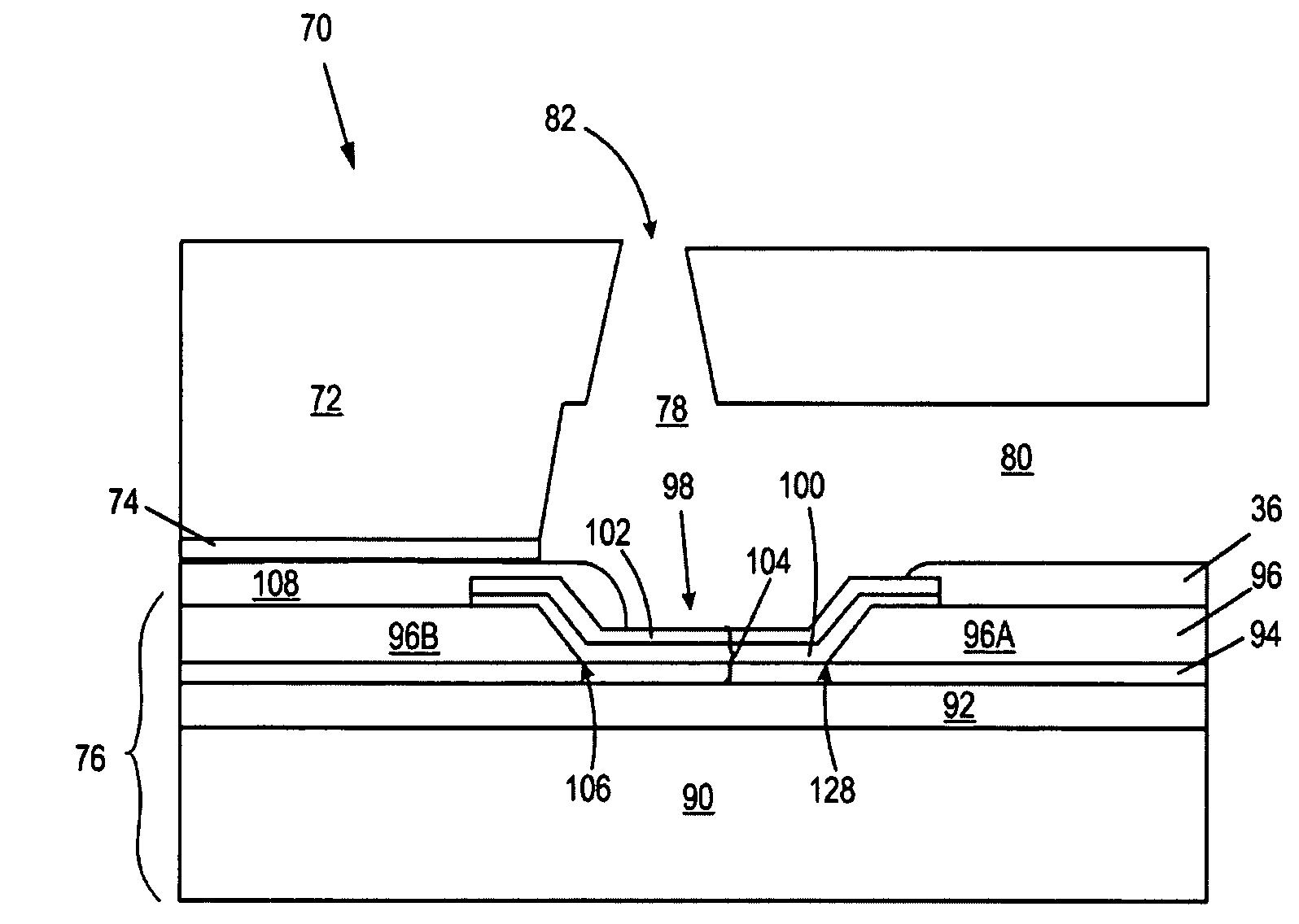
[0022]In accordance with embodiments described herein, micro-fluid ejection heads having improved energy consumption and extended life will now be described.

[0023]For the purposes of this disclosure, the terms “heater stack”, “ejector stack”, and “actuator stack” are intended to refer to an ejection actuator having a combined layer thickness of a resistive material layer and passivation or protection material layer. The passivation or protection material layer is applied to a surface of the resistive material layer to protect the actuator from, for example, chemical or mechanical corrosion or erosion effects of fluids ejected by the micro-fluid ejection device.

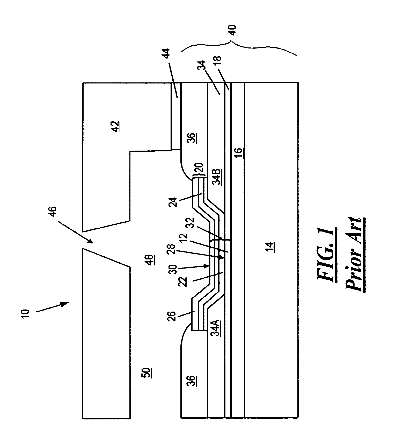
[0024]In order to more fully appreciate the benefits of the exemplary embodiments, reference is first made to FIG. 1, which is a cross-sectional view, not to scale, of a portion of a prior art micro-fluid ejection head 10. The cross-sectional view of FIG. 1 shows one of many micro-fluid ejection actuators 12 contained on a mic...


PUM


Abstract

Micro-fluid ejection heads and methods for extending the life of micro-fluid ejection heads. One such micro-fluid ejection head includes a substrate having a plurality of thermal ejection actuators. Each of the thermal ejection actuators has a resistive layer and a protective layer thereon. A flow feature member is adjacent the substrate and defines a fluid feed channel, a fluid chamber associated with at least one of the actuators and in flow communication with the fluid feed channel, and a nozzle. The nozzle is offset to a side of the chamber opposite the feed channel. A polymeric layer having a degradation temperature of less than about 400° C. overlaps a portion of the at least one actuator associated with the fluid chamber and positioned less than about five microns from at least an edge of the at least one actuator opposite the fluid feed channel.

Description

FIELD OF THE DISCLOSURE[0001]The disclosure relates to micro-fluid ejection devices and in one particular embodiment, to low energy, long life devices for ejecting small liquid droplets.BACKGROUND AND SUMMARY[0002]Micro-fluid ejection devices are classified by a mechanism used to eject fluid. Two of the major types of micro-fluid ejection devices include thermal actuators and piezoelectric actuators. Thermal actuators rely on an ability to heat the fluid to a nucleation temperature wherein a gas bubble is formed that expels the fluid through a nozzle. The life of such thermal actuators is dependent on a number of factors including, but not limited to, dielectric breakdown, corrosion, fatigue, electromigration, contamination, thermal mismatch, electro static discharge, material compatibility, delamination, and humidity, to name a few. A heater resistor used in a micro-fluid ejection device may be exposed to all of these failure mechanisms.[0003]For example, it is well-known that cavi...

Claims


Application Information

Patent Timeline
Patent Type & Authority Applications(United States)
IPC IPC(8): B41J2/05
CPCB41J2/1404B41J2002/14387B41J2002/14185B41J2/14129
Inventor CORNELL, ROBERT W.POWERS, JAMES HAROLDMULAY, SHIRISH PADMAKARCORNELL, ROBERT L.
Owner SLINGSHOT PRINTING LLC
Learn More