Serializer and deserializer

a serializer and deserializer technology, applied in the field of serializers and deserializers, can solve the problems of cumbersome application of 8b/10b on each independent lane, excessive power consumption in coding/decoding, and reduce the bandwidth of the channel, so as to reduce power consumption

Inactive Publication Date: 2008-10-23
MULTIGIG INC
View PDF3 Cites 14 Cited by
  • Summary
  • Abstract
  • Description
  • Claims
  • Application Information

AI Technical Summary

Benefits of technology

[0010]A new approach takes advantage of differential of AC coupled signals but without loss of bit-rate and a dramatic reduction in power consumption relativ

Problems solved by technology

Line coding schemes, such as 8b/10b, consume too much power in coding/decoding and reduce bandwidth of the channel.
It is also cumbersome to apply 8b/10b on each independent lane.
However, in pathological cases, the output can be DC for long intervals of time, which often leads

Method used


Image

  • Serializer and deserializer
  • Serializer and deserializer
  • Serializer and deserializer

Examples


Embodiment Construction

Transmitter

[0030]One objective of the present invention is power savings. The first power-saving possibility comes from transmitting signal levels that are much smaller than VDD. FIG. 2 illustrates a SERDES transmitter 50 in accordance with an embodiment of the present invention. There are three SERDES channels 52, 54, 56 shown, though the mid-stage channel 54 is optional. The transmitter 58, 60, 62 for each channel is designed to transmit a differential positive or negative voltage on a 100 ohm differential pair 64, 66, 68. The figure shows how a full-bridge FET switch 70-76, 78-84, 86-92 can drive a push-pull differential signal with small swings, i.e., without the need of a full VDD swing. The circuits are double pull-double throw (DPDT) analog switches whose series resistance is set to suit the transmission-line medium's characteristic impedance. Choosing the transistor sizes to have nominally 50 ohms on-resistance provides a ‘back-termination’ resistance to the transmission-lin...


PUM


Abstract

A system and method of transmitting and receiving bit serial information is disclosed. In a differential embodiment, serial bits are transmitted by a pair of line-matched differential drivers that are ac coupled to a two-conductor transmission line. A receiver is ac coupled to the line and receives the transmitted serial information via a high pass filter. The receiver includes a level-triggered latch that provides a threshold for receiving the serial information, changes state to reflect the received information, and then clamps the received information to the state of the latch. In a single-ended embodiment, the ac-coupled receiver receives the bit serial information via a high pass filter. The resistance for the filter is an active device that also provides a voltage threshold for the receiver. The received bit serial information changes the state of a device which then alters the threshold, via hysteresis, for the net bit of serial information.

Description

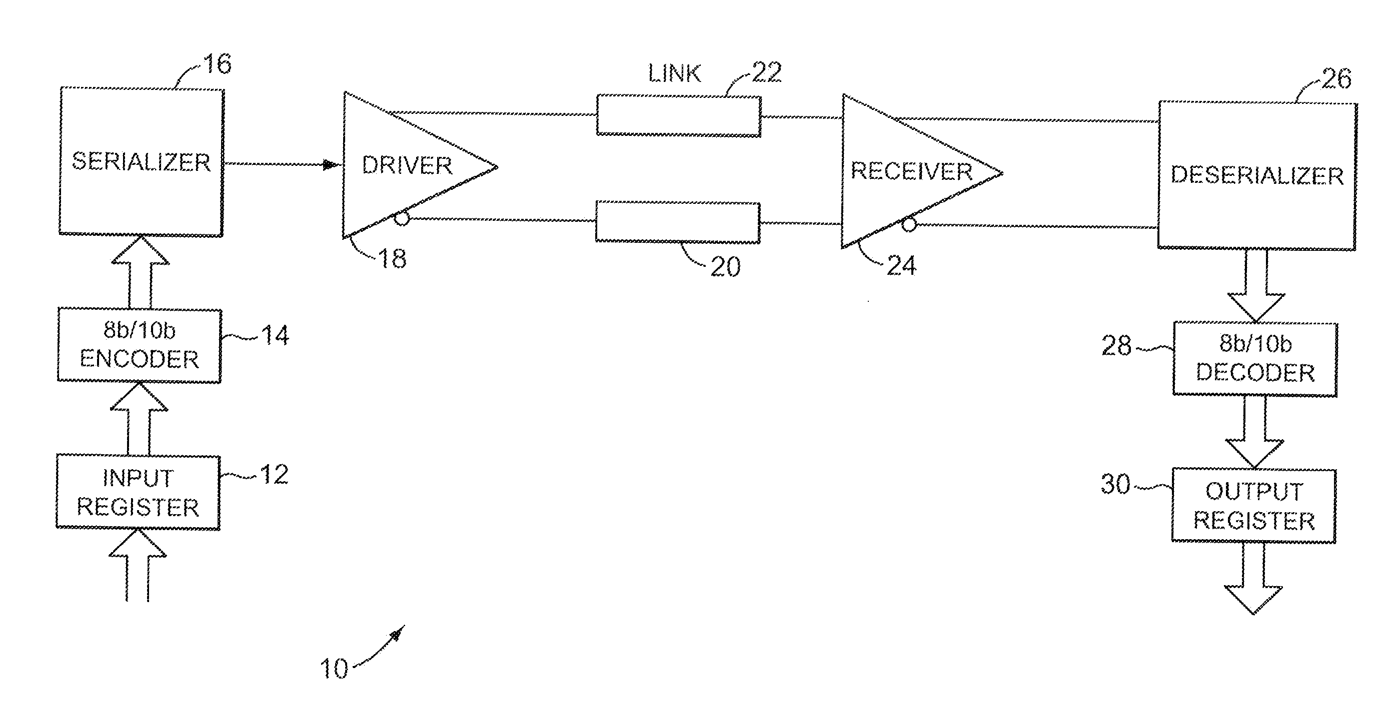
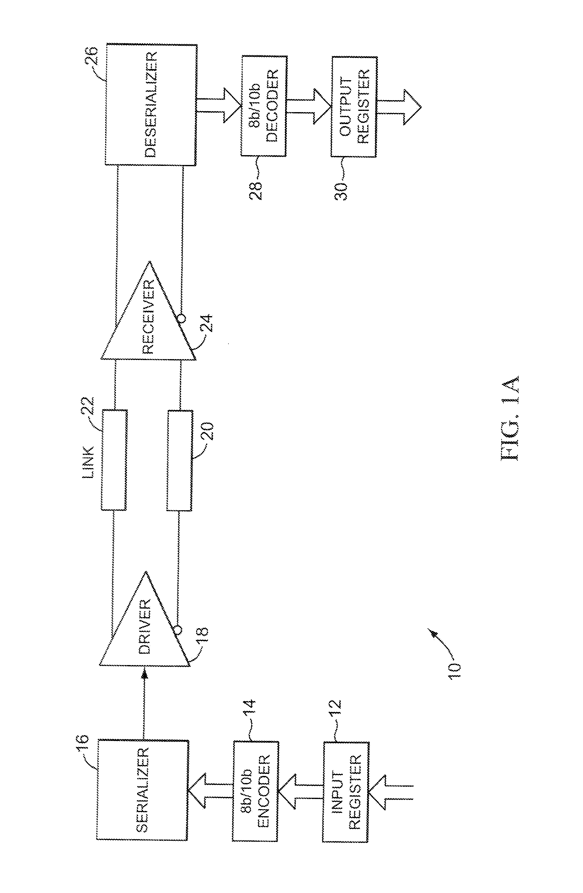
CROSS-REFERENCES TO RELATED APPLICATIONS[0001]This application is a continuation of U.S. application Ser. No. 11 / 755,505, filed May 30, 3007, which is a continuation of U.S. application Ser. No. 11 / 530,781, filed Sep. 11, 2006, which claims the benefit of U.S. Provisional Application No. 60 / 716,552, filed Sep. 19, 2005, which provisional application is hereby incorporated by reference in its entirety.FIELD OF THE INVENTION[0002]The present invention relates generally to a system and method for converting digital data from parallel to serial and serial to parallel and more particular to a SERDES transmission system.DESCRIPTION OF THE RELATED ART[0003]FIG. 1A shows a conventional SERDES channel 10, which includes an input register 12, an encoder 14, a serializer 16, a driver 18, transmission line links 20, 22, receiver 24, a deserializer 26, a decoder 28 and an output register 30. The term SERDES is usually taken to mean a high-speed serial I / O channel using differential transmission ...

Claims


Application Information

Patent Timeline
IPC IPC(8): H04B3/50
CPCG06F13/4072H04L25/0266H04L25/0272Y02B60/1235H04L25/0292Y02B60/1228H04L25/028Y02D10/00
Inventor WOOD, JOHN
Owner MULTIGIG INC
Why Eureka
Try Eureka