Electroosmotic Pump System and Electroosmotic Pump

a pump system and electroosmotic technology, applied in the field electroosmotic pump, can solve the problems of high cost of electroosmotic pump system b>250/b>, system cannot be reduced in overall size, etc., and achieve the effect of improving fluid controllability and increasing the mobility of the entire system

Inactive Publication Date: 2008-10-23
NANO FUSION TECH
View PDF30 Cites 62 Cited by
  • Summary
  • Abstract
  • Description
  • Claims
  • Application Information

AI Technical Summary

Benefits of technology

[0066]If the liquid reservoir is disposed upstream of the first fluid passage, then the liquid supplied to the liquid reservoir reaches an upstream end of the electroosmotic member due to its own weight or a capillary effect. Even if no voltage is applied between the first electrode and the second electrode, the liquid that has reached the upstream surface of the electroosmotic member penetrates the electroosmotic member due to a capillary effect therein, and reaches a downstream end of the electroosmotic member. Therefore, with the liquid reservoir being filled with the liquid in advance, no liquid supply lines are needed for supplying the liquid from an external source to the electroosmotic pump. The mobility of the entire system is thus further increased.
[0067]A lid covering the opening is effective to prevent the liquid from being evaporated from the liquid reservoir and also to prevent dust from entering the liquid after the liquid reservoir has been filled with the liquid.
[0068]Preferably, a space extending from the discharge port to the second fluid passage has a volume v in the range of 10 [nl]<v<10 [μl], or a distance from the discharge port to the second fluid passage ran...

Problems solved by technology

Even if the fluid interfaces are improved, therefore, the system cannot be reduced in overall size.
However, the electroosmotic pump system 250 is problematic in that it poses limitations on t...

Method used


Image

  • Electroosmotic Pump System and Electroosmotic Pump
  • Electroosmotic Pump System and Electroosmotic Pump
  • Electroosmotic Pump System and Electroosmotic Pump

Examples


first embodiment

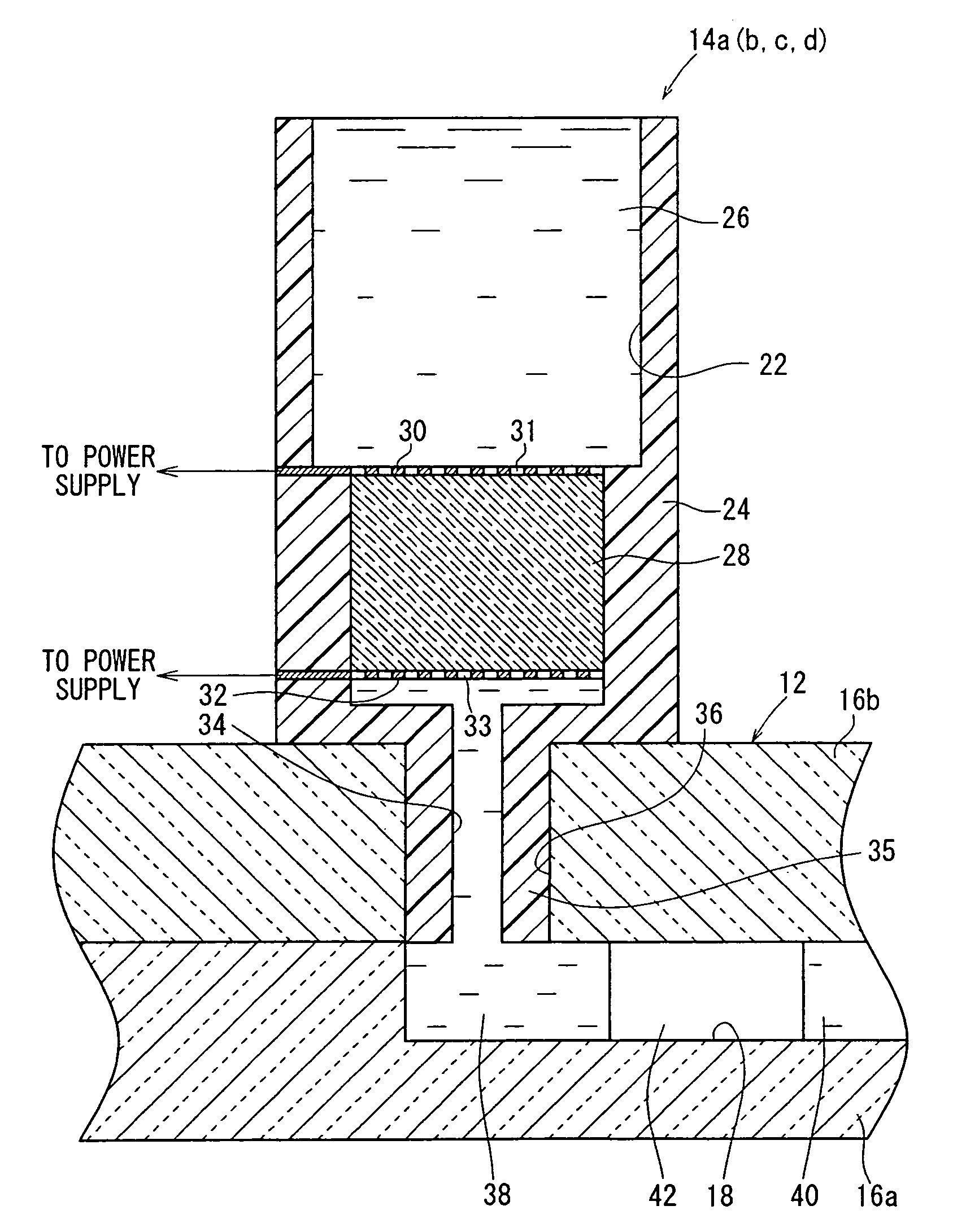
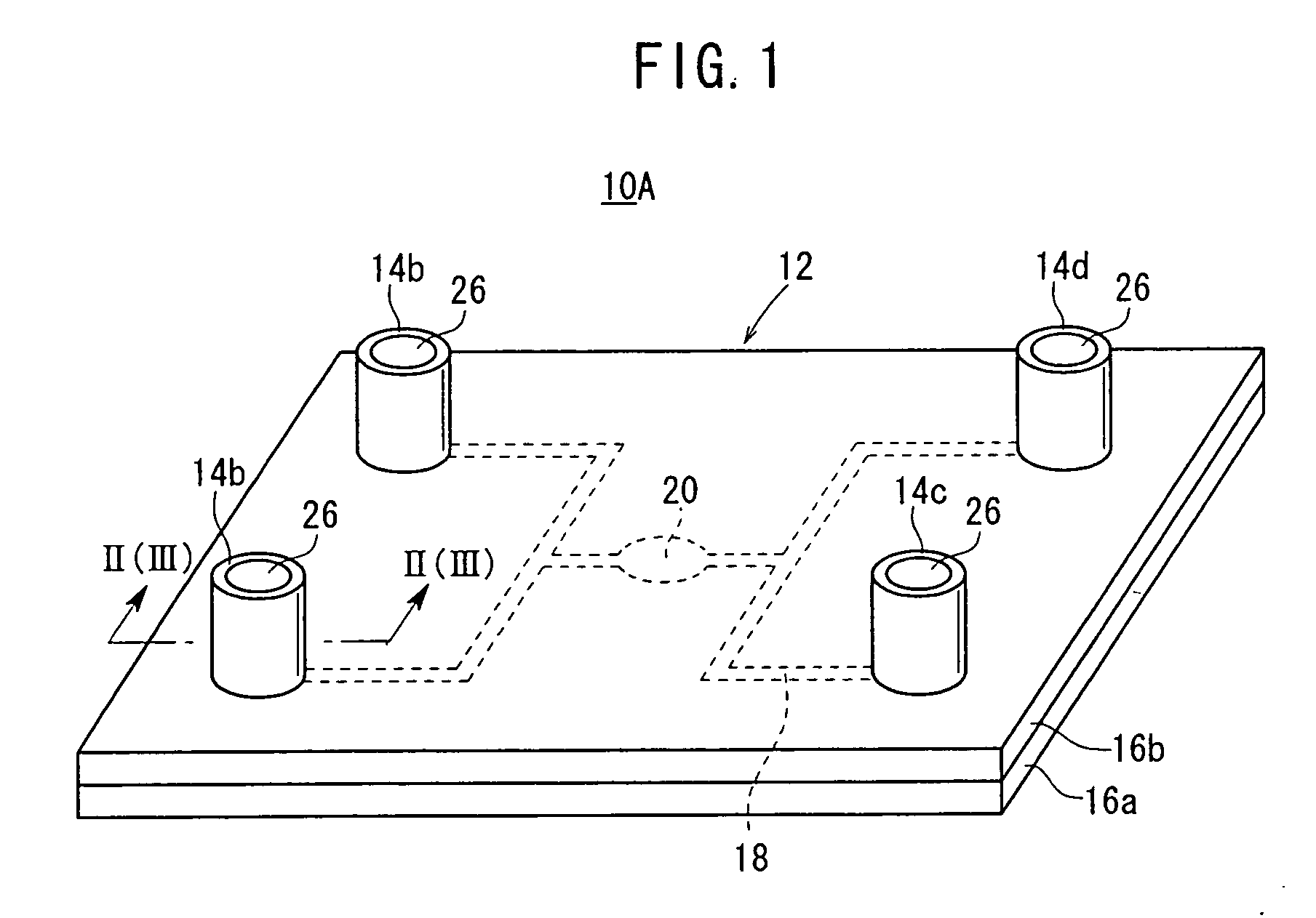
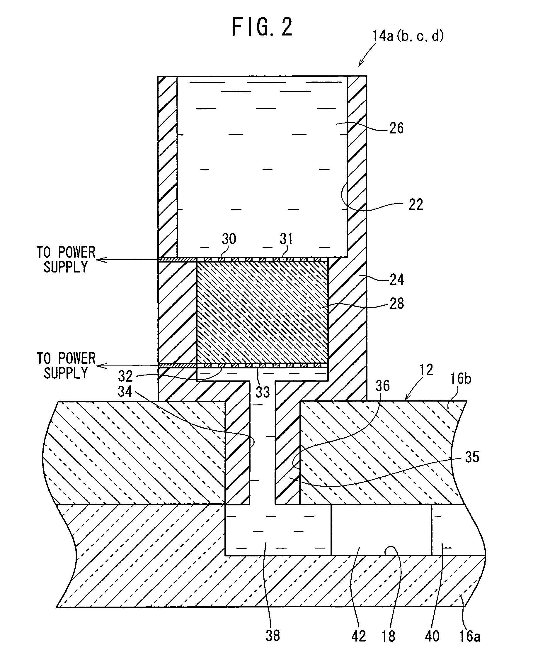
[0103]As shown in FIGS. 1 and 2, an electroosmotic pump system 10A comprises four electroosmotic pumps 14a through 14d directly mounted on an upper surface of a microfluidic chip 12.

[0104]The microfluidic chip 12 is of a size of about 10 [cm]×5 [cm]×2 [mm], and comprises glass substrates 16a, 16b whose respective upper and lower surfaces are bonded or thermally fused to each other. The glass substrate 16a has a groove of predetermined shape defined in the upper surface thereof. The glass substrate 16b has holes defined therein in facing relation to the opposite ends of the groove. When the glass substrate 16a and the glass substrate 16b are joined to each other, the groove, the lower surface of the glass substrate 16b, and the holes jointly make up a second fluid passage 18. The holes serve as communication holes 36 of the second fluid passage 18 which communicate with the electroosmotic pumps 14a through 14d. As shown in FIG. 1, a reactor 20 which is part of the groove and is coup...

second embodiment

[0172]With the electroosmotic pump system 10B as described above, when the electroosmotic pumps 14a through 14d are directly mounted on the microfluidic chip 12 through the bosses 35, the third terminal 56a, 64a is electrically connected to the first electrode 30 through the first terminal 54a, 58a through 62a, and the fourth terminal 56b, 64b is electrically connected to the second electrode 32 through the second terminal 54b, 58b through 62b. If the third terminal 56a, 64a and the fourth terminal 56b, 64b are electrically connected to an external power supply, then the power supply can apply a voltage of one polarity to the first electrode 30 through the third terminal 56a, 64a and the first terminal 54a, 58a through 62a and a voltage of the opposite polarity to the second electrode 32 through the fourth terminal 56b, 64b and the second terminal 54b, 58b through 62b, thereby actuating the electroosmotic pumps 14a through 14d. Therefore, the bosses 35 function as an interface for ...

third embodiment

[0174]An electroosmotic pump system 10C will be described below with reference to FIGS. 11 and 12.

[0175]As shown in FIGS. 11 and 12, the electroosmotic pump system 10C according to the third embodiment differs from the electroosmotic pump system 10A according to the first embodiment (see FIGS. 1 through 6) and the electroosmotic pump system 10B according to the second embodiment (see FIGS. 7 through 10) in that it has a microfluidic chip 12 held by a holder member 63 and an electroosmotic pump 14 secured to and held on the holder member 63 by a support member 67, a first terminal 65a, and a second terminal 65b.

[0176]The holder member 63 comprises a substantially rectangular block with a recess 75 defined centrally therein for accommodating the microfluidic chip 12 therein. Specifically, the holder member 63 is a packaging member used for mounting the microfluidic chip 12 in position. The holder member 63 serves to secure and protect the microfluidic chip 12 and functions as an int...


PUM


Abstract

A projection is formed on a pump body of an electroosmotic flow pump so as to face a communication hole of a micro fluid chip. When the projection and the communication hole are fitted together, a first flow path of the pump and a second flow path of the micro fluid chip are communicated and the pump is fixed to the micro fluid chip. At the same time, the connection between the first flow path and the second flow path is sealed to prevent leakage of liquid gas, etc. to the outside.

Description

TECHNICAL FIELD[0001]The present invention relates to an electroosmotic pump system and an electroosmotic pump for supplying a fluid to or drawing a fluid from a microfluidic chip thereby to control the fluid in the microfluidic chip, e.g., to control the flow rate, pressure, and level of the fluid in the microfluidic chip.BACKGROUND ART[0002]Microfluidic chips are used to provide microscale fluid passages and various fluid control devices on plastic or glass chips for causing chemical reactions or biochemical reactions to occur in the fluid control devices. Use of a microfluidic chip is effective to reduce the size of a system for developing chemical reactions or biochemical reactions and also to greatly reduce the amounts of a sample and a reagent required in such chemical reactions or biochemical reactions. As a result, the time required by the system for measurements and the power consumption of the system can be reduced.[0003]The system needs a pump for driving the fluid in the...

Claims


Application Information

Patent Timeline
IPC IPC(8): F04F11/00B81B1/00B01J19/00F04F99/00B01L3/00B01L9/00F04B19/00G01N35/08G01N37/00
CPCB01J2219/00891B01L3/5027B01L3/565B01L9/527B01L2200/027B01L2300/0816B01L2400/0418F04B19/006B01J19/00B81B1/00G01N35/08G01N37/00
Inventor NISHIKAWA, MASANAYANAGISAWA, ICHIRO
Owner NANO FUSION TECH
Why Eureka
Try Eureka