Biomechanical design of intracorneal inlays

a biomechanical design and inlay technology, applied in the field of corneal implants, can solve the problems of hyperopia (farsightedness), vision impairment, etc., and achieve the effect of increasing the diopter power of the cornea and the curvature of the anterior corneal surfa

Inactive Publication Date: 2008-10-23
REVISION OPTICS
View PDF99 Cites 26 Cited by
  • Summary
  • Abstract
  • Description
  • Claims
  • Application Information

AI Technical Summary

Benefits of technology

[0007]In one embodiment, inlays having diameters smaller than the diameter of the pupil are provided for correcting presbyopia. To provide near vision, an inlay is implanted centrally in the cornea to induce an “effect” zone on the anterior corneal surface that is smaller than the optical zone of the cornea, wherein the “effect” zone is the area of the anterior corneal surface affected by the inlay. The implanted inlay increases the curvature of the anterior corneal surface within the “effect” zone, thereby increasing the diopter power of the cornea within the “effect” zone. Because the inlay's “effect” zone is also smaller than the diameter of the pupil, light rays from distance objects by-pass the inlay and refract using the region of the cornea peripheral to the “effect” zone to create an image of the distant objects on the retina.

Problems solved by technology

As is well known, abnormalities in the human eye can lead to vision impairment.
Some typical abnormalities include variations in the shape of the eye, which can lead to myopia (near-sightedness), hyperopia (farsightedness) and astigmatism as well as variations in the tissue present throughout the eye, such as a reduction in the elasticity of the lens, which can lead to presbyopia.

Method used


Image

  • Biomechanical design of intracorneal inlays
  • Biomechanical design of intracorneal inlays
  • Biomechanical design of intracorneal inlays

Examples


Embodiment Construction

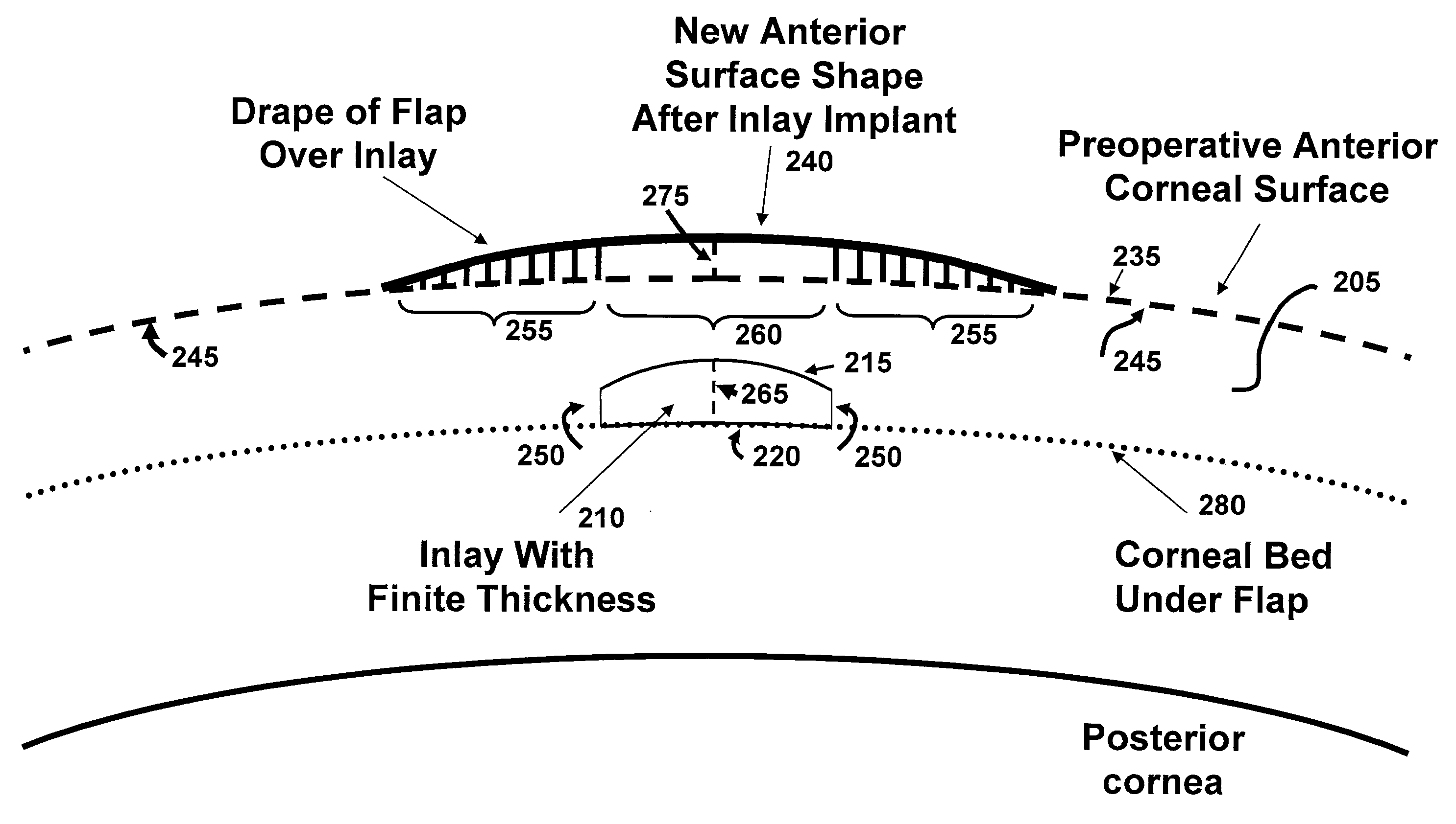
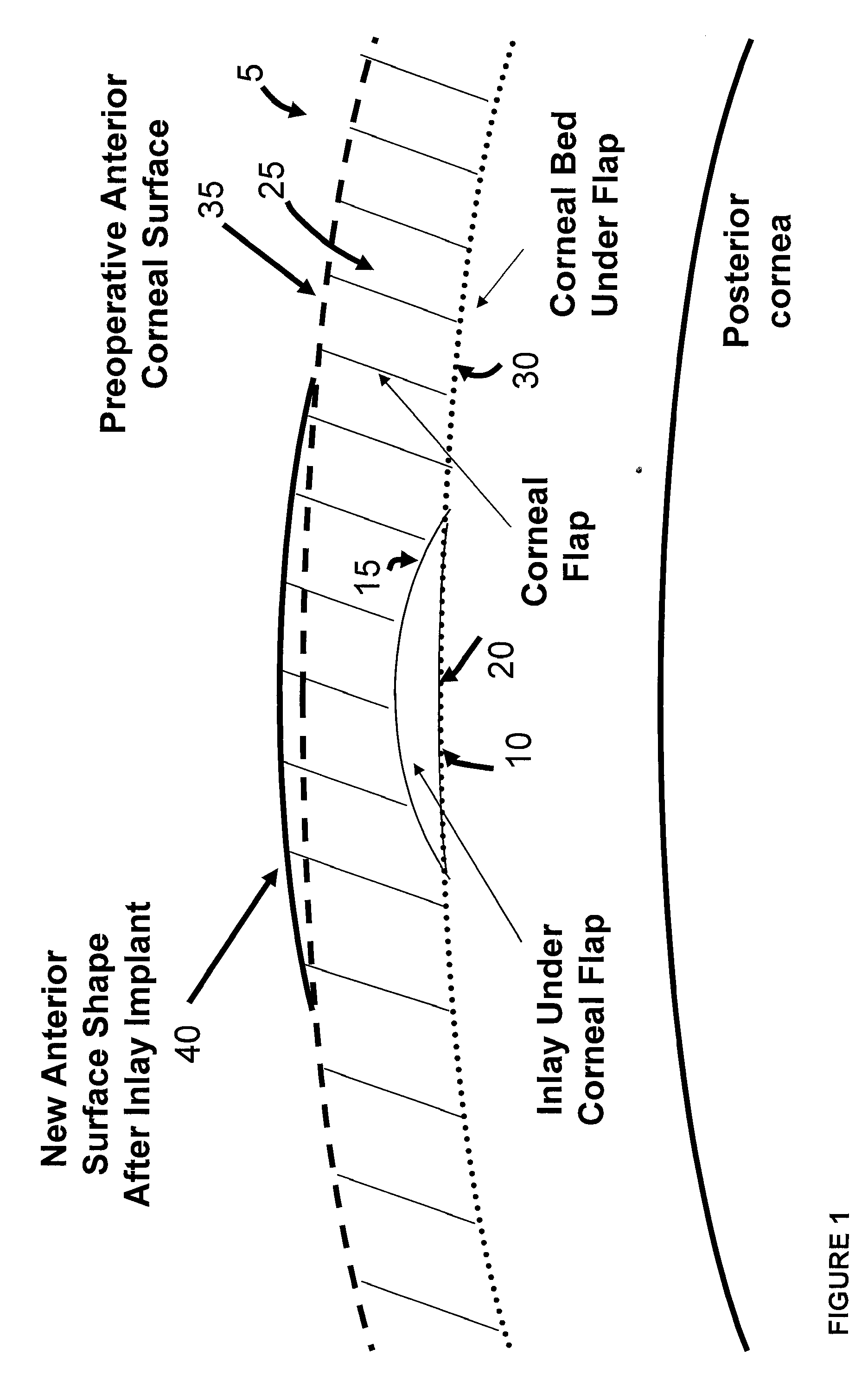
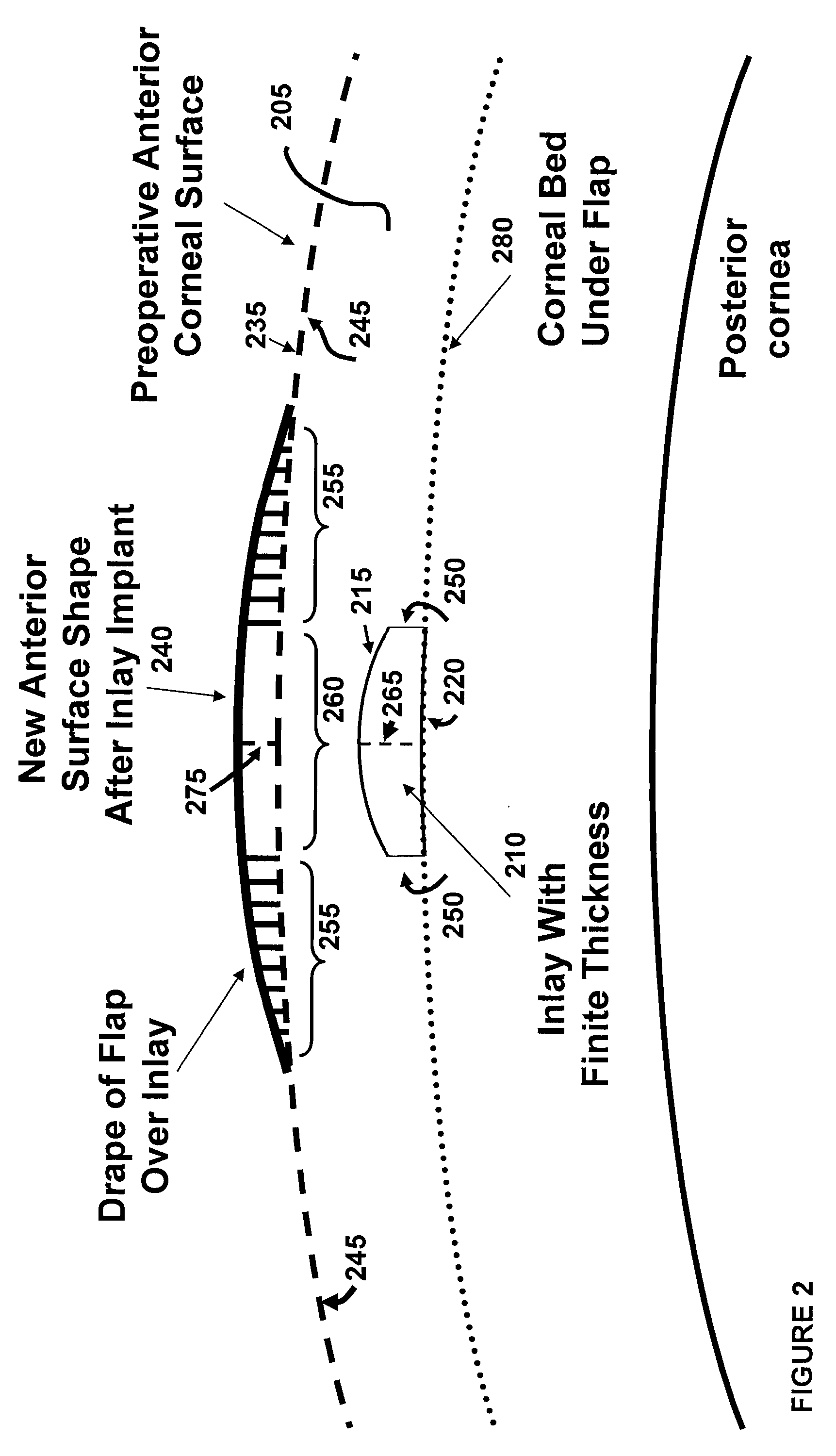
[0034]FIG. 1 show an example of an intracorneal inlay 10 implanted in a cornea 5. The inlay 10 may have a meniscus shape with an anterior surface 15 and a posterior surface 20. The inlay 10 is preferably implanted in the cornea at a depth of 50% or less of the cornea thickness (approximately 250 μm or less), and is placed on the stromal bed 30 of the cornea created by a keratome. The inlay 10 may be implanted in the cornea 5 by cutting a flap 25 into the cornea, lifting the flap 25 to expose the cornea's interior, placing the inlay 10 on the exposed area of the cornea's interior with the inlay centered on the subject's pupil or visual axis, and repositioning the flap 25 over the inlay 10. The flap 25 may be cut using a laser, e.g., a femtosecond laser, a mechanical keratome or manually by an ophthalmic surgeon. When the flap 25 is cut into the cornea, a small section of corneal tissue is left intact to create a hinge for the flap 25 so that the flap 25 can be repositioned accurately...


PUM


Abstract

Provided herein are intracorneal inlays for correcting vision impairments by altering the shape of the anterior corneal surface. The physical design of the inlay to induce the desired change of the anterior corneal surface includes consideration of the biomechanical response of the corneal tissue to the physical shape of the inlay. This biomechanical response can differ depending on the thickness, diameter, and profile of the inlay. In one embodiment, inlays having diameters smaller than the pupil are provided for correcting presbyopia. To provide near vision, an inlay is implanted centrally in the cornea to induce an “effect” zone on the anterior corneal surface, within which diopter power is increased. Distance vision is provided by a region of the cornea peripheral to the “effect” zone. In another embodiment, small diameter inlays are provided that induce “effect” zones on the anterior corneal surface that are much larger in diameter than the inlays.

Description

FIELD OF THE INVENTION[0001]The field of the invention relates generally to corneal implants, and more particularly, to intracorneal inlays.BACKGROUND INFORMATION[0002]As is well known, abnormalities in the human eye can lead to vision impairment. Some typical abnormalities include variations in the shape of the eye, which can lead to myopia (near-sightedness), hyperopia (farsightedness) and astigmatism as well as variations in the tissue present throughout the eye, such as a reduction in the elasticity of the lens, which can lead to presbyopia. A variety of technologies have been developed to try and address these abnormalities, including corneal implants.[0003]Corneal implants can correct vision impairment by altering the shape of the cornea. Corneal implants can be classified as an onlay or an inlay. An onlay is an implant that is placed over the cornea such that the outer layer of the cornea, e.g., the epithelium, can grow over and encompass the implant. An inlay is an implant t...

Claims


Application Information

Patent Timeline
Patent Type & Authority Applications(United States)
IPC IPC(8): A61F2/14
CPCA61F2/147
Inventor LANG, ALANMILLER, TROYSCHNEIDER, NEDVATZ, ALEXANDERICENOGLE, TONYA BROOKEFRANZ, SYLVIAJOHNSON, DERRICK
Owner REVISION OPTICS
Why Eureka
Try Eureka