Reducing the Cost of Distributed Electricity Generation Through Opportunity Generation

a technology of opportunity generation and distributed electricity, which is applied in the direction of ac network with energy trading/transmission rights, reactive power adjustment/elimination/compensation, electric power transfer ac network, etc. it can solve the problems of high fuel cost, short bursts of very high prices, and unnecessary expense of stand-by generating facilities. , to achieve the effect of increasing the cost of diesel and more economic outcomes

Inactive Publication Date: 2008-10-23
PERERA ANIL L M
View PDF3 Cites 49 Cited by
  • Summary
  • Abstract
  • Description
  • Claims
  • Application Information

AI Technical Summary

Benefits of technology

[0030]The widely used alternating current induction motor in common with other more sophisticated electric motor/generators, has the ability to also run as an electricity generator when driven by a prime mover above its synchronous speed. The invention uses this characteristic to convert almost any electric motor driven application into an economic opportunity drive cum generating system (Opportunity Generation) by adding a substitutable prime mover to the motor driven application thereby enabling the selection of the more economical fuel source to service the given load and when circumstances are appropriate to enable the system is run as an electricity generator with or without the prime mover also servicing the application load at the same time. Whether the load needs to run simultaneously while generating electricity will dependent on the load requirements at that instant, whether intermediate storage facilities can allow intermittent running of the load, and whether there are other drives (prime movers and/or motors) installed for reliability reasons. Whether the load can run simultaneously while the prime mover is also generating electricity will depend also on facilities available for speed control of the generator shaft and the availability of power output regulating means eg a converter-inverter system. Since most motor applications are for time variant loads, the motor drive systems are designed to operate in a ‘on’ and ‘off’ cycle usually controlled by minimum and maximum values of a relevant parameter eg. t

Problems solved by technology

With gradual increases in the level of reliability of electricity supplied through the mains, stand-by generating facilities gradually came to be regarded as an unnecessary expense.
The dilemma with tying to maximise the use of stand-by generators is that while they are able to respond to high pool prices (automatically if using the method described in Australian Patent No 748800), the extra capital cost of the generator set remains a financial burden.
Very occasionally there are short bursts of very high prices when higher cost generators bidding a very high price also need to be dispatched to meet load requirements.
Given that using coal for small power supply systems is not practical and the price of gas which is supplied via the distribution system to retail customers can be substantially higher than the price of gas supplied to power stations via trunk mains, instances of co-generation has been few and far between.
“Large wing turbine” is not included in the figure (as it is in Table 2) because it is not generally considered to be well-suited to distributed generation applications (typically, it is not located near customers).aIn a combined-cycle system, a combustion turbine is operated in tandem with a steam turbine.
The problem with the systems described above, is that the increase in the efficiency of fuel use and any relief available by way of ‘carbon credits’ or such schemes, are not sufficient to offset the higher cost of fuel petrol, diesel, LPG or retailed natural gas) at the small retail customer level.
Another disadvantage in some of these schemes is the fact that the possible electricity output is constrained by the amount of useful sustainable heat recovery.
On site generation has a

Method used


Image

  • Reducing the Cost of Distributed Electricity Generation Through Opportunity Generation
  • Reducing the Cost of Distributed Electricity Generation Through Opportunity Generation
  • Reducing the Cost of Distributed Electricity Generation Through Opportunity Generation

Examples


Embodiment Construction

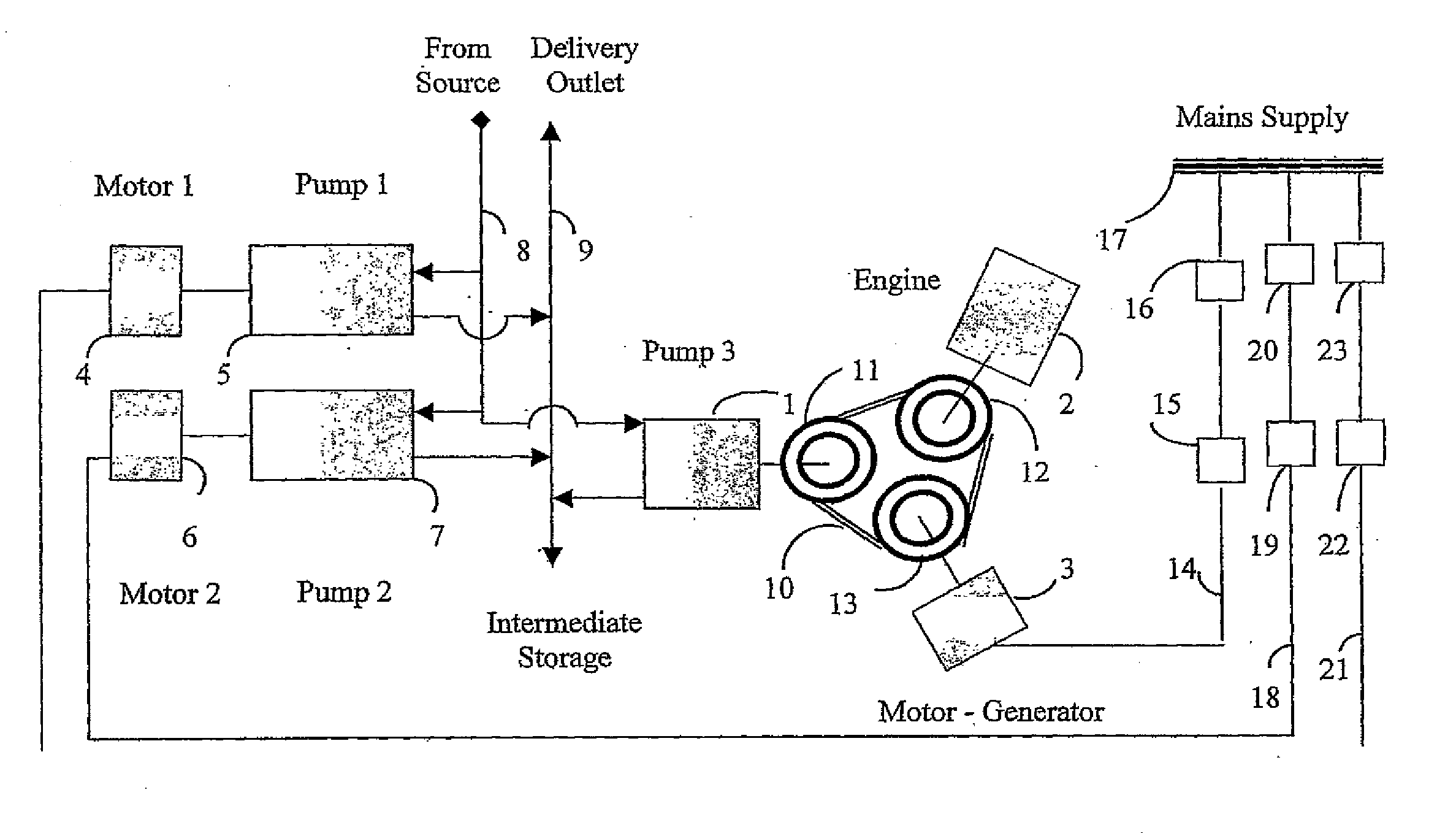
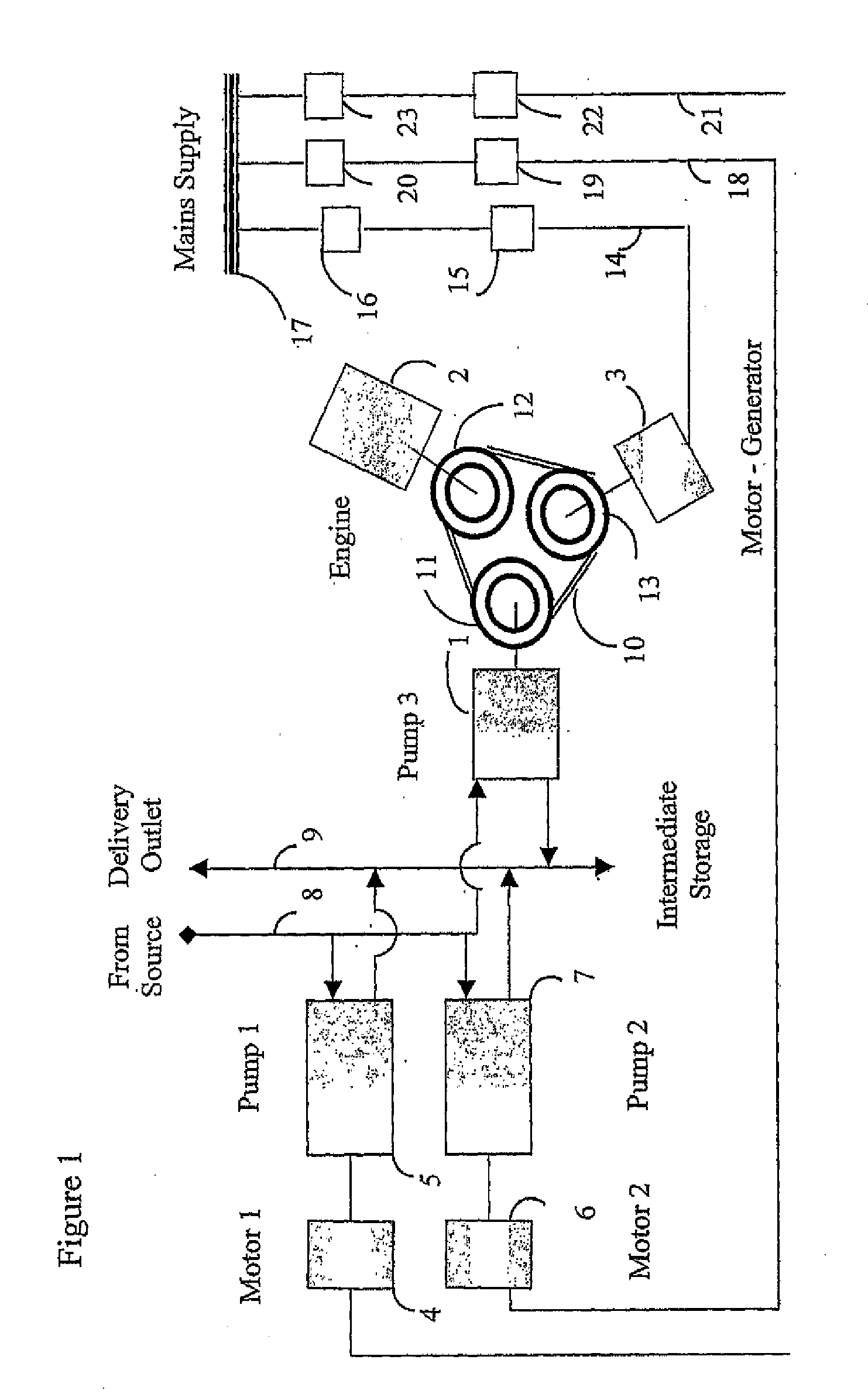
[0036]For purposes of clarity, the working of the invention is first described in its application to a simple embodiment of the invention in a high reliability environment such as a water pumping station, as depicted in FIG. 1. The normal design for such a pumping station would have three motor driven pumps, where two pumps would be needed to run in tandem to supply peak load but for most of the time operating one pump is sufficient to meet load requirements (a typical arrangement if there was no intermediate storage). A spare pump-set caters for a situation such as a breakdown of one pump or when one pump is down for routine maintenance. Motors 4,6 drive pumps 5,7 and are supplied electricity by means of the lines 21, 18 from the mains supply 17 via isolators 20,23 and starter units 19, 22

[0037]The electricity mains supply to the pump station would normally be sourced from two alternate feeders following different paths preferably originating from two distribution substations. Depe...


PUM


Abstract

A new disposition of energy use and electricity cogeneration facilities at a customer's premises that enables even a small customer to choose one or more forms of primary energy from among available energy sources, so as to reduce the overall capital and operating costs of meeting own load requirements. Takes into consideration opportunities to save money by way of reducing own load and/or opportunities to earn money by exporting electricity to the mains grid whenever electricity market prices are high, and/or benefiting from payment for network support and ancillary services where such schemes apply. For operations requiring a high level of reliability, opportunity is provided to achieve a desired level of reliability for operations at the premises without recourse to extra cost of duplicate electricity supply connecting lines or expensive stand-by power generation facilities.

Description

FIELD OF THE INVENTION[0001]The present invention relates to a new disposition of energy conversion and electricity generation facilities at a customer's premises, that reduces the overall cost of energy use by the customer, improves the customer's reliability of supply and can also contribute to improving the reliability of the power system. The invention extends the scope for distributed generation and co-generation by reducing both the initial capital cost and the significant operating cost premium when undertaking electricity cogeneration at the user premises. The invention allows the end customer to be the ultimate arbitrager able to choose whether to use electricity or another primary fuel to satisfy a significant portion of energy requirements at the premises based on price differentials in die respective energy markets.BACKGROUND DESCRIPTION[0002]During the early stages of development of the electricity supply industry (ESI), the reliability of the power supply system was lo...

Claims


Application Information

Patent Timeline
IPC IPC(8): G06Q50/00H02J3/20G06Q30/00G06Q50/06H02J3/36
CPCG06Q30/00H02J3/008Y04S50/10H02J3/38
Inventor PERERA, ANIL L.M.
Owner PERERA ANIL L M
Why Eureka
Try Eureka