Method to identify and generate critical timing path test vectors

a technology of critical timing path and test vector, which is applied in the field of method to identify and generate critical timing path test vector, can solve the problems of cumbersome process of identifying critical (cycle time limit) paths in hardware, inability to account for timing sensitivities, and conventional systems employ laborious methods of locating critical paths. , to achieve the effect of improving the performance of each circuit design, facilitating the integration of chip timing data, and reducing tester tim

Inactive Publication Date: 2008-10-23
IBM CORP
View PDF27 Cites 12 Cited by
  • Summary
  • Abstract
  • Description
  • Claims
  • Application Information

AI Technical Summary

Benefits of technology

[0012]Accordingly, the embodiments of the invention help reduce tester time when bringing up new designs and facilitate the integration of chip timing data into automated chip test pattern processes. The embodiments herein use critical timing path data for creating test patterns which directly address the frequency limiting portions of the circuits to improve the performance of each circuit design. Conventional processes of testing which use actual hardware are time consuming, so only a few samples can be tested with conventional methods. To the contrary, with the embodiments herein, simulation is used to identify which test signals cause the most stress on the critical paths, which is a faster process and more efficient than conventional methods.

Problems solved by technology

Current methods of generating such test patterns can fail to account for timing sensitivities.
However, the process of identifying such critical (cycle time limiting) paths in hardware can be cumbersome.
Thus, as can be seen by the process disclosed in Kapur '437, the conventional systems utilize laborious methods of locating and testing critical paths.
Conventional processes of testing which use actual hardware are time consuming, so only a few samples can be tested with conventional methods.

Method used


Image

  • Method to identify and generate critical timing path test vectors
  • Method to identify and generate critical timing path test vectors
  • Method to identify and generate critical timing path test vectors

Examples


Embodiment Construction

[0025]The embodiments of the invention and the various features and advantageous details thereof are explained more fully with reference to the non-limiting embodiments that are illustrated in the accompanying drawings and detailed in the following description. It should be noted that the features illustrated in the drawings are not necessarily drawn to scale. Descriptions of well-known components and processing techniques are omitted so as to not unnecessarily obscure the embodiments of the invention. The examples used herein are intended merely to facilitate an understanding of ways in which the embodiments of the invention may be practiced and to further enable those of skill in the art to practice the embodiments of the invention. Accordingly, the examples should not be construed as limiting the scope of the embodiments of the invention.

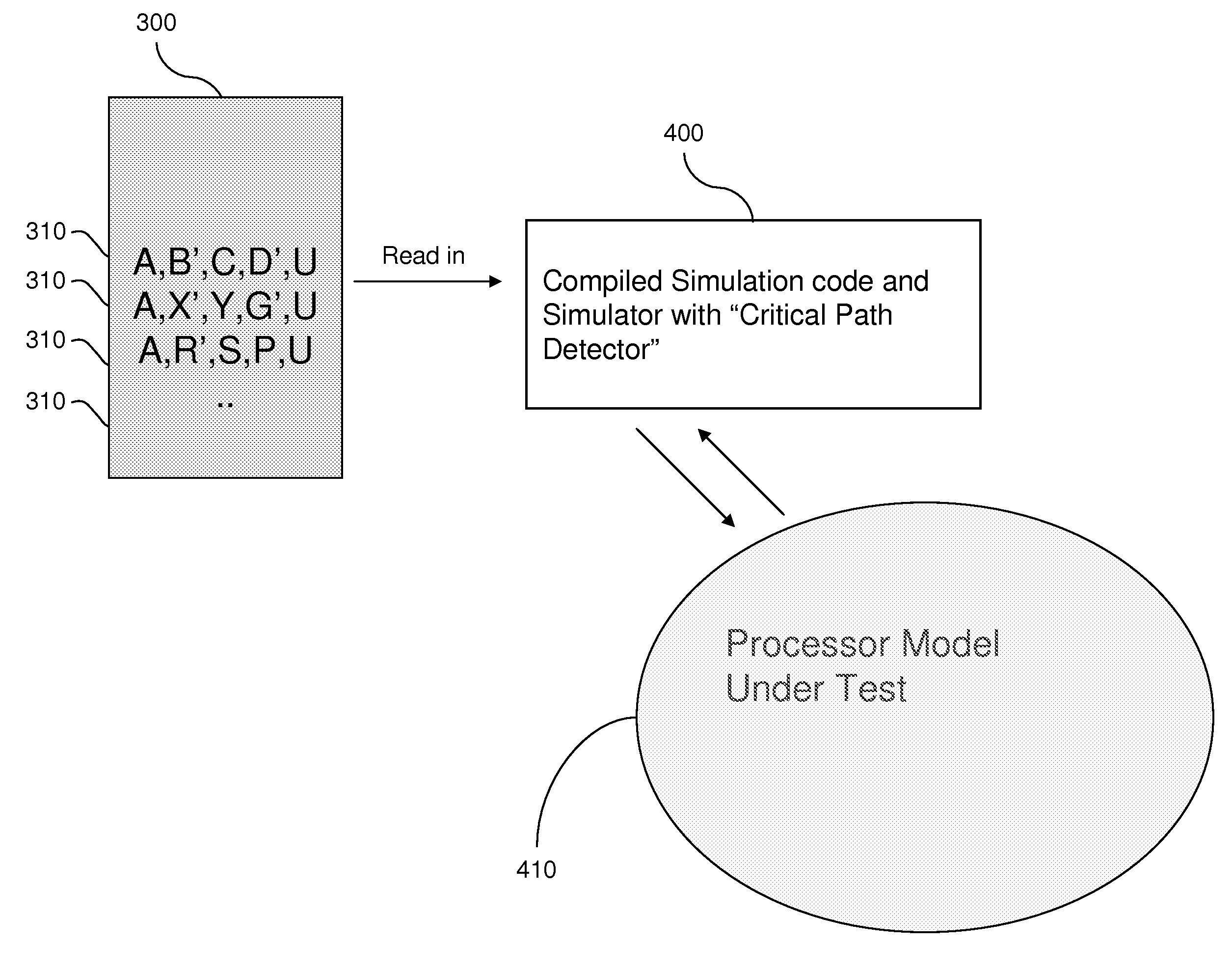
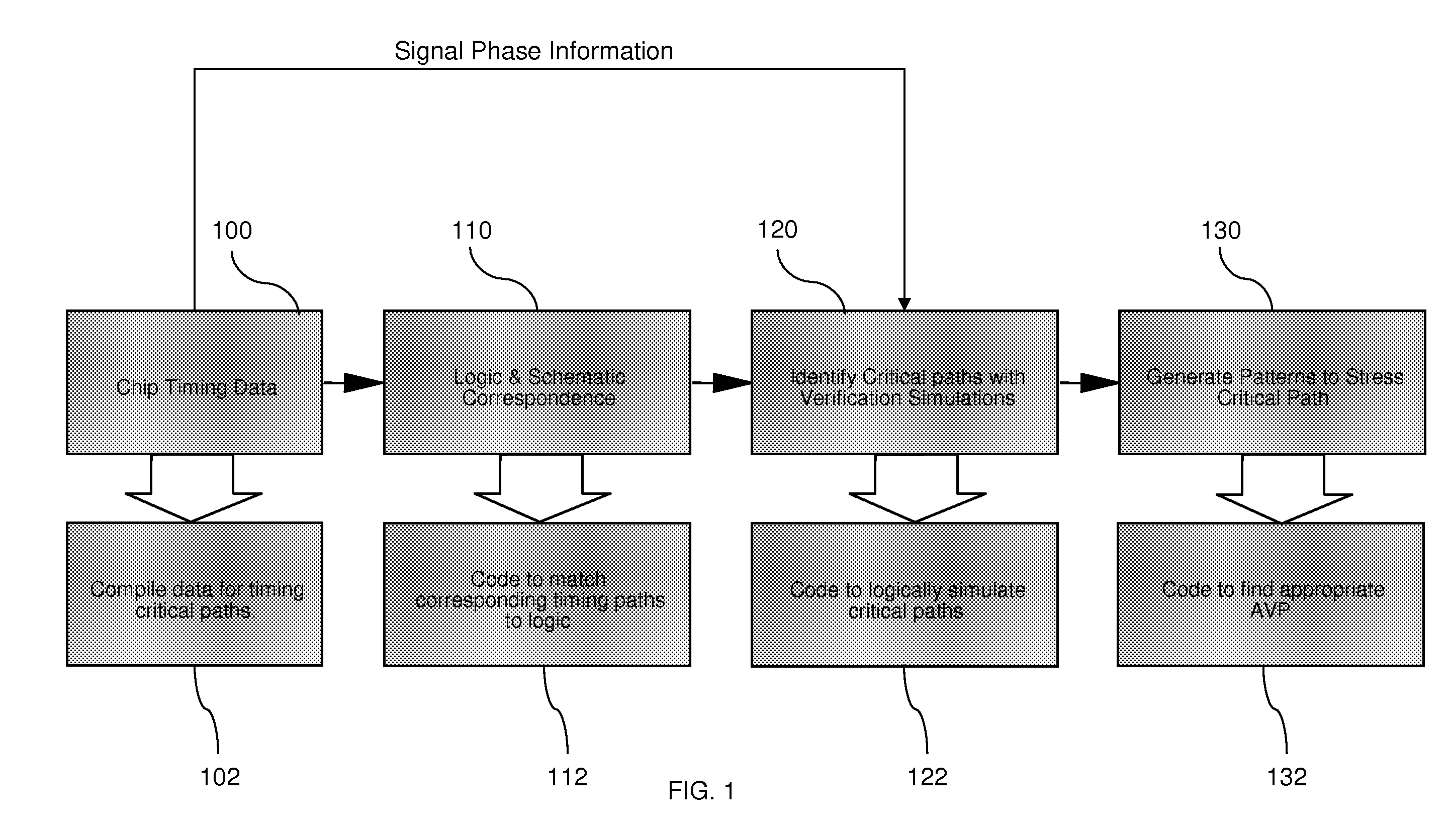
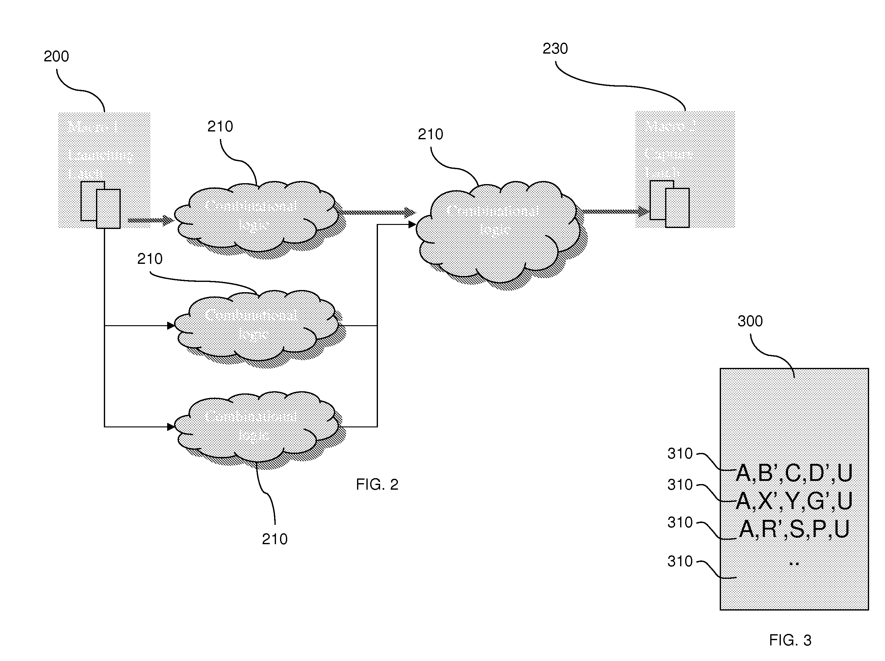
[0026]As discussed above, conventional methodologies present slow and cumbersome processes for identifying and testing critical paths in integra...


PUM


Abstract

A method of testing critical paths in integrated circuits begins by simulating at least one operation of an integrated circuit chip design to produce chip timing data. Next, critical paths of the integrated circuit chip design are identified based on the chip timing data. The method applies functional test signals to simulations of the critical paths and monitors the number of times each of the functional test signals propagate from the beginning to the end of each of the critical paths. This allows the method to identify stress producing test signals as those that propagate along the critical paths more than other test signals. These stress producing test signals are applied to integrated circuit chip hardware manufactured according to the integrated circuit chip design to stress test the hardware.

Description

BACKGROUND[0001]1. Field of the Invention[0002]The embodiments of the invention provide a method, program storage device, etc., to identify and generate critical timing path test vectors for integrated circuit devices.[0003]2. Description of the Related Art[0004]When manufacturing sophisticated devices, such as integrated circuits on chips, many factors in the design and manufacturing process can affect the performance and operability of the devices. One factor that has been found to play a role in high quality integrated circuit devices relates to the timing differences of communication and other signals as they travel across the circuits. Therefore, it is common to find and test the routes or “paths” within the circuit along which the various signals will travel to ensure that the most important paths or bottleneck paths (e.g., the critical paths) operate properly. Such critical paths are often tested by applying test pattern signals (test patterns) to the actual, physically manuf...

Claims


Application Information

Patent Timeline
Patent Type & Authority Applications(United States)
IPC IPC(8): G06F17/50
CPCG01R31/318364G06F17/5031G06F30/3312
Inventor CANADA, MILES G.GOVETT, IAN R.SARGIS, JOHNSEITZER, DARYL M.SINGLEY, DANEYAND J.TANPURE, ABHIJEET R.VISWANATH, MANIKANDAN
Owner IBM CORP
Why Eureka
Try Eureka