
Apparatus for Protein Separation Using Capillary Isoelectric Focusing-Hollow Fiber Flow Field Flow Fractionation and Method Thereof

a technology of capillary isoelectric focusing and fluorescent fibers, applied in the direction of fluid pressure measurement, liquid/fluent solid measurement, peptides, etc., can solve the problems of protein trapped in the gel, difficult to separate and discern the mixture of numerous different proteins comprising a proteome, and labor-intensive 2d-page techniqu

Inactive Publication Date: 2008-10-30
IND ACADEMIC CORP FOUND YONSEI UNIV
View PDF6 Cites 28 Cited by
  • Summary
  • Abstract
  • Description
  • Claims
  • Application Information

AI Technical Summary

Problems solved by technology

This technique suffers from disadvantages in that proteins in SDS solutions are denatured, and thus have tertiary structures different from the native structures thereof, and proteins are trapped within the gel.
With the one-dimensional technique alone, it is difficult to separate and discern the mixture of numerous different proteins comprising a proteome, which is defined as the entire complement of proteins expressed by a genome, the production and relative amounts of individual proteins thereof varying depending on the physiological conditions of cells or tissues.
However, 2D-PAGE is a labor-intensive technique, and is not only difficult to automate, but also has limitations in detection sensitivity and dynamically active, range.
Furthermore, the separated proteins trapped within the gel matrix are difficult to recover.
However, the capacity of CIEF is insufficient to treat a complex mixture of proteins, such as a proteome, and thus an attempt has recently been made to conduct CIEF in association with a secondary separation technique, such as chromatography, rather than alone, in order to enhance synergic separation efficiency.
This technique is difficult to apply to proteins because their chains are broken and lost upon passage through the column.
However, this combination suffers from the disadvantage of requiring an additional purification process for removing the ampholytes used in the CIEF after the completion of separation.
Therefore, unless the ampholytes are removed in advance, it is difficult to perform a sample analysis due to the interruption of ions in the solution.
This technique, although able to separate proteins, cannot avoid the denaturation of proteins due to the organic solvent used in RPLC, and is still inapplicable to the separation of large molecular weight proteins.
However, this method is not as high in resolution power as is required, and is incapable of separation on the basis of various protein properties.

Method used


Image

  • Apparatus for Protein Separation Using Capillary Isoelectric Focusing-Hollow Fiber Flow Field Flow Fractionation and Method Thereof
  • Apparatus for Protein Separation Using Capillary Isoelectric Focusing-Hollow Fiber Flow Field Flow Fractionation and Method Thereof
  • Apparatus for Protein Separation Using Capillary Isoelectric Focusing-Hollow Fiber Flow Field Flow Fractionation and Method Thereof

Examples


example 1

Construction of Protein Separation Apparatus

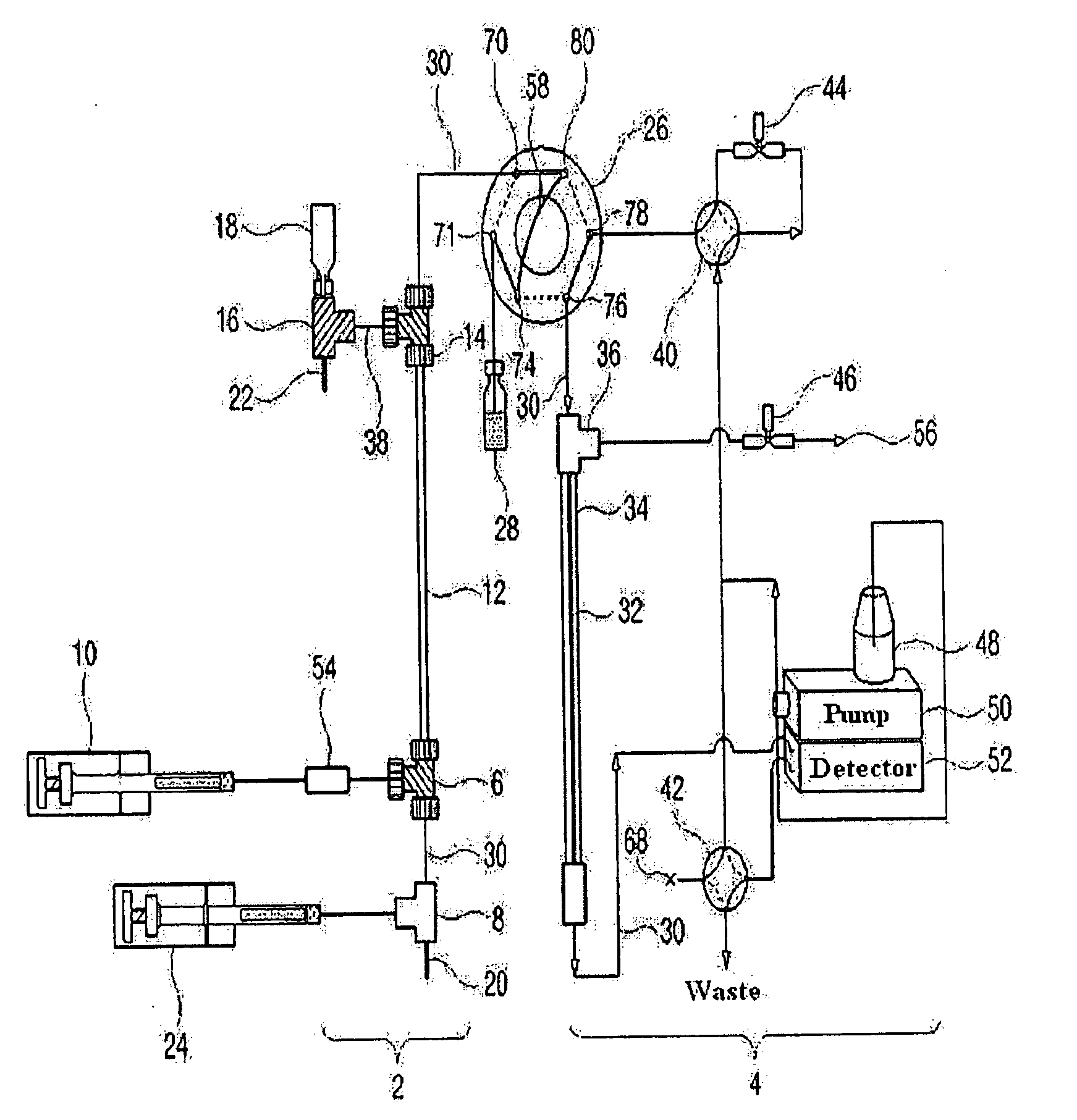
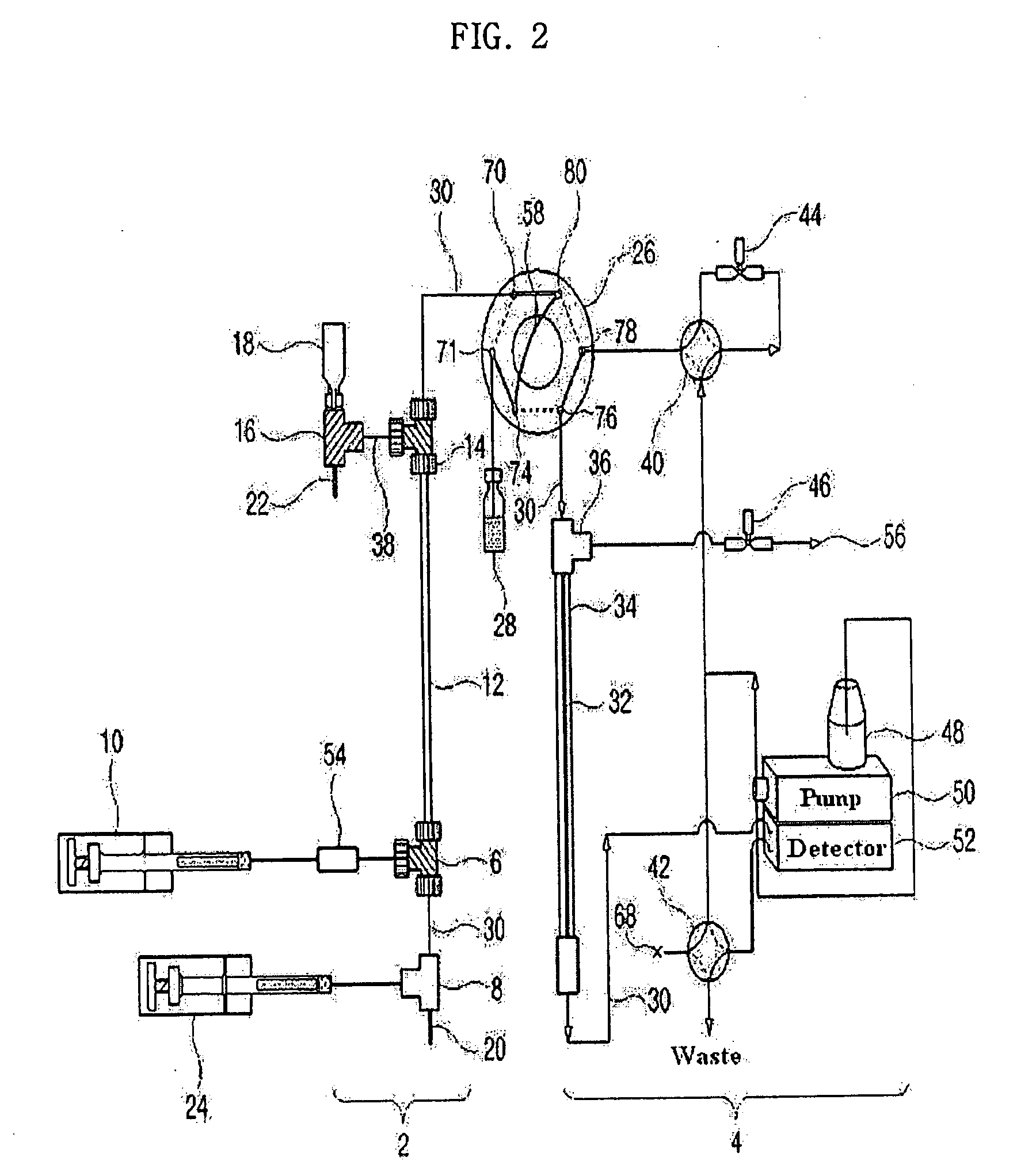
[0134]As shown in FIG. 2, a 9.5 cm×310 μm (inner diameter) Teflon capillary [Vernon Hills, Cole-Parmer, USA], serving as an isoelectric focusing capillary, was provided at one end thereof with two MicroTees [Upchurch Scientific, USA] in sequence, which were connected with each other via a silica capillary [Phoenix, Polymicro Technologies, USA] having an outer diameter of 360 μm and an inner diameter of 50 μm.

[0135]Next, a union [Delrin Standard Union, Upchurch Scientific, USA] and a syringe pump [Harvard Apparatus 22, Harvard Apparatus, USA] were sequentially connected to one side of the first MicroTee. The second MicroTee [Upchurch Scientific, USA] was connected at one side to a syringe pump [Harvard Apparatus 22, Harvard Apparatus, USA] and at another side to a platinum electrode serving as an anode. The syringe pump communicating with the first MicroTee was filled with protein samples [myoglobin (15 kDa, pI 6.8), trypsinogen (24 kDa. pI...

example 2

Separation of Protein Standards by Capillary Isoelectric Focusing-Hollow Fiber Flow Field Flow Fractionation Apparatus

[0141]A mixture of five protein standards was prepared as a specimen for testing the resolving power of the protein separation apparatus (capillary isoelectric focusing-hollow fiber flow field flow fractionation apparatus) constructed in Example 1. The composition of the protein mixture is given in Table 1, below.

TABLE 1ProteinsPropertiesContent (ng)1Myoglobin15 kDA, pI6.81252Trypsinogen24 kDA, PI9.82003Carbonic anhydrase29 kDA, pI5.85504Bovine Serum albumin66 kDA, pI4.81805Yeast alcohol dehydrogenase150 kDA, pI6.23250

[0142]After being loaded with the protein mixture of Table 1 and an ampholyte (5% v / v), the first syringe pump of the protein separation apparatus, constructed as in Example 1, was operated to supply the mixture solution to the Teflon capillary. Then, the isoelectric focusing of the protein mixture was performed by applying an electric field of 500 V / cm...

example 3

Separation of Human Urinary Proteins by Capillary Isoelectric Focusing-Hollow Fiber Flow Field Flow Fractionation Apparatus

[0157]The protein separation apparatus constructed in Example 1 (capillary isoelectric focusing-hollow fiber flow field flow fractionation apparatus) was applied for the separation of the proteins extracted from human urine.

[0158]In order to employ protein samples having a molecular weight of 30 kDa or greater, urine was filtered through a membrane with 30 kDa cutoff.

[0159]The same procedure as in Example 2 was performed, with the exception that 40 μg of the filtered urinary protein sample was used instead of the protein mixture and isoelectric focused protein fractions had six respective pH zones. Protein fractions with a pH range of 9-10, 8-9, 7-8, 6-7, 5-6 and 3-5 were injected in that order and separated by hollow fiber flow field flow fractionation.

[0160]The results are shown in FIG. 7. Nanoflow LC-MS-MS was used for protein identification.

[0161]As seen in ...


PUM

PropertyMeasurementUnit
Fractionaaaaaaaaaa
Fractionaaaaaaaaaa
Timeaaaaaaaaaa

Abstract

Disclosed herein is an apparatus for the separation of proteins, comprising a capillary isoelectric focusing unit (2) for primarily separating protein samples on the basis of pi; and a hollow fiber flow field flow fractionation unit (4), connected to one side of the capillary isoelectric focusing unit (2), for secondarily separating the protein samples. The apparatus allows proteins to be separated on the basis of pi and molecular weight without denaturation and can further be applied for the identification of proteins in conjunction with nanoflow liquid chromatography-electrospray ionization-tandem mass spectrometry after enzymatic digestion of the protein fractions.

Description

TECHNICAL FIELD[0001]The present invention relates to an apparatus and a method for the separation of a protein mixture using capillary isoelectric focusing-hollow fiber flow field flow fractionation. More particularly, the present invention relates to an apparatus and a method for separating a macromolecular protein mixture, such as proteomes, on the basis of pI and molecular weight, without denaturing proteins.BACKGROUND ART[0002]Currently, one of the most interesting concerns in the life and medical sciences is the systemic analysis of proteins involved in diseases because they can be used in the treatment and prevention of the diseases.[0003]With the great advances in fundamental sciences that contribute to drug discovery, including molecular biology and genomics (genome science), the category of drug discovery has expanded and changed rapidly. Particularly, genomic drugs, typifying new drugs, require new and different methods for the discovery thereof.[0004]To be developed into...

Claims


Application Information

Patent Timeline
IPC IPC(8): B01D57/02
CPCB01D63/02C07K1/28G01N27/44773G01N27/44795B01D2313/18C07K1/14C12M1/00
Inventor MOON, MYEONG HEEKANG, DUK JIN
Owner IND ACADEMIC CORP FOUND YONSEI UNIV
Learn More