Circuit-Arrangement for Modulating an Led and Method for Operating Same

a technology of circuit arrangement and led, applied in the direction of electric variable regulation, process and machine control, instruments, etc., can solve the problems of current spikes and difficulty in achieving high modulation frequencies, and achieve good modulation properties

Active Publication Date: 2008-10-30
SIGNIFY HLDG BV
View PDF9 Cites 8 Cited by
  • Summary
  • Abstract
  • Description
  • Claims
  • Application Information

AI Technical Summary

Benefits of technology

[0005]It is an object of this invention to provide a circuit-arrangement, which enables good modulation properties.

Problems solved by technology

Although the shown approach ensures a constant current through each LED, a disadvantage of this circuit is that a high frequency modulation of the LEDs may cause problems with current spikes.
Therefore, it may be difficult to achieve high modulation frequencies.

Method used


Image

  • Circuit-Arrangement for Modulating an Led and Method for Operating Same
  • Circuit-Arrangement for Modulating an Led and Method for Operating Same
  • Circuit-Arrangement for Modulating an Led and Method for Operating Same

Examples


Embodiment Construction

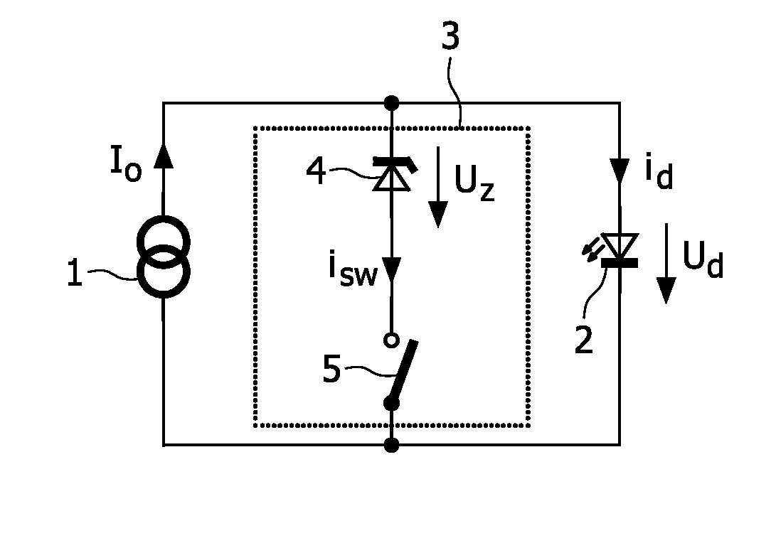
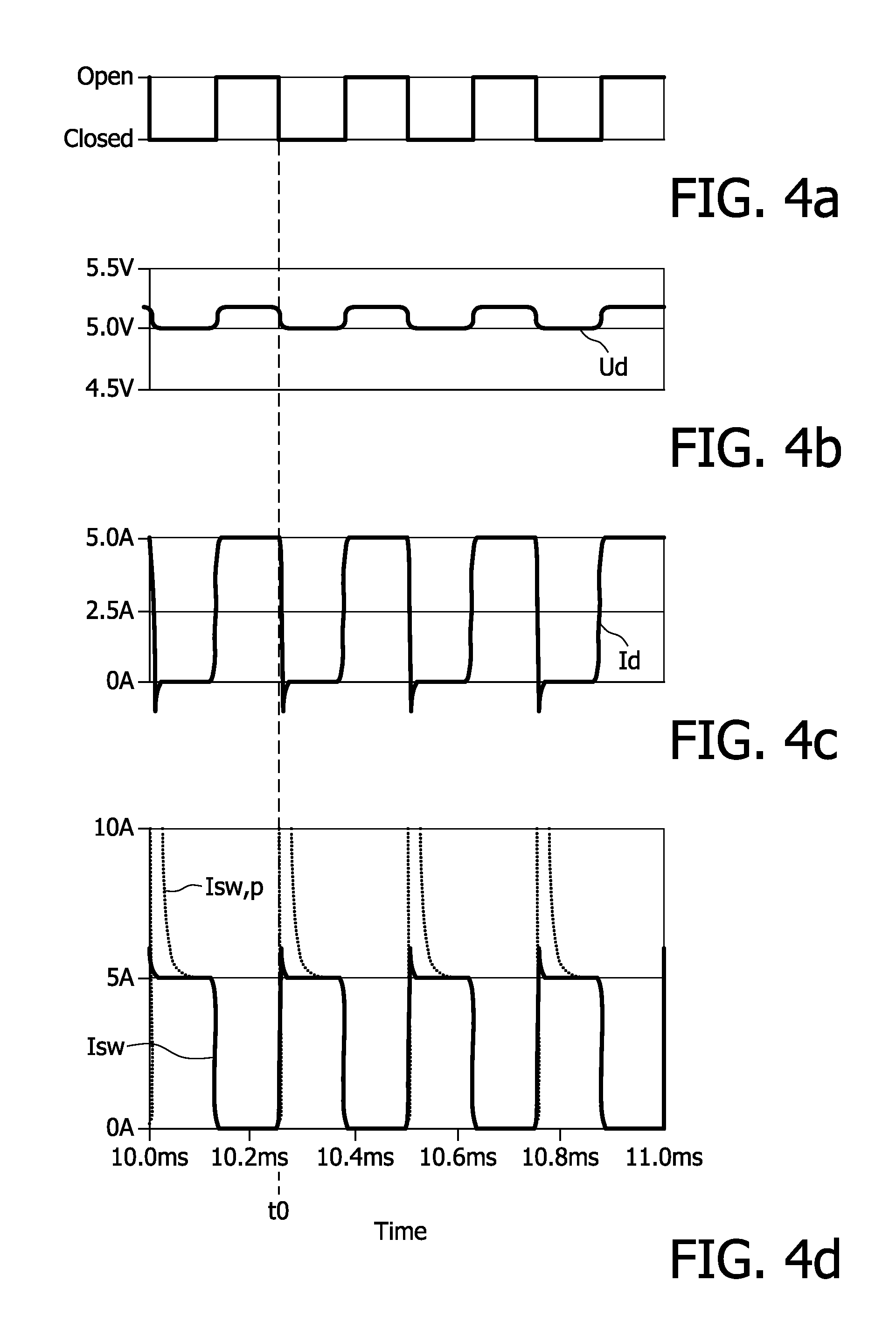
[0031]FIG. 1 shows a circuit diagram of an embodiment of a circuit-arrangement according to the invention. Here, a current source 1 supplies a current I0=5 A to a parallel connection of an OLED 2 and a modulation-circuit 3, which comprises a zener diode 4 and a switch 5. The switch 5 serves as a switching device and enables at least an open state and a closed state. In the closed state, the modulation-circuit 3 short-circuits the OLED 2, so that the OLED 2 is not illuminated. For modulation of the OLED 2 in terms of dimming, the switch 5 is periodically alternated between the open and the closed state. The zener diode 4 is arranged in reverse bias direction to the forward direction of the OLED 2 and exhibits a zener voltage Uz=5V with a corresponding zener current of 1 A.

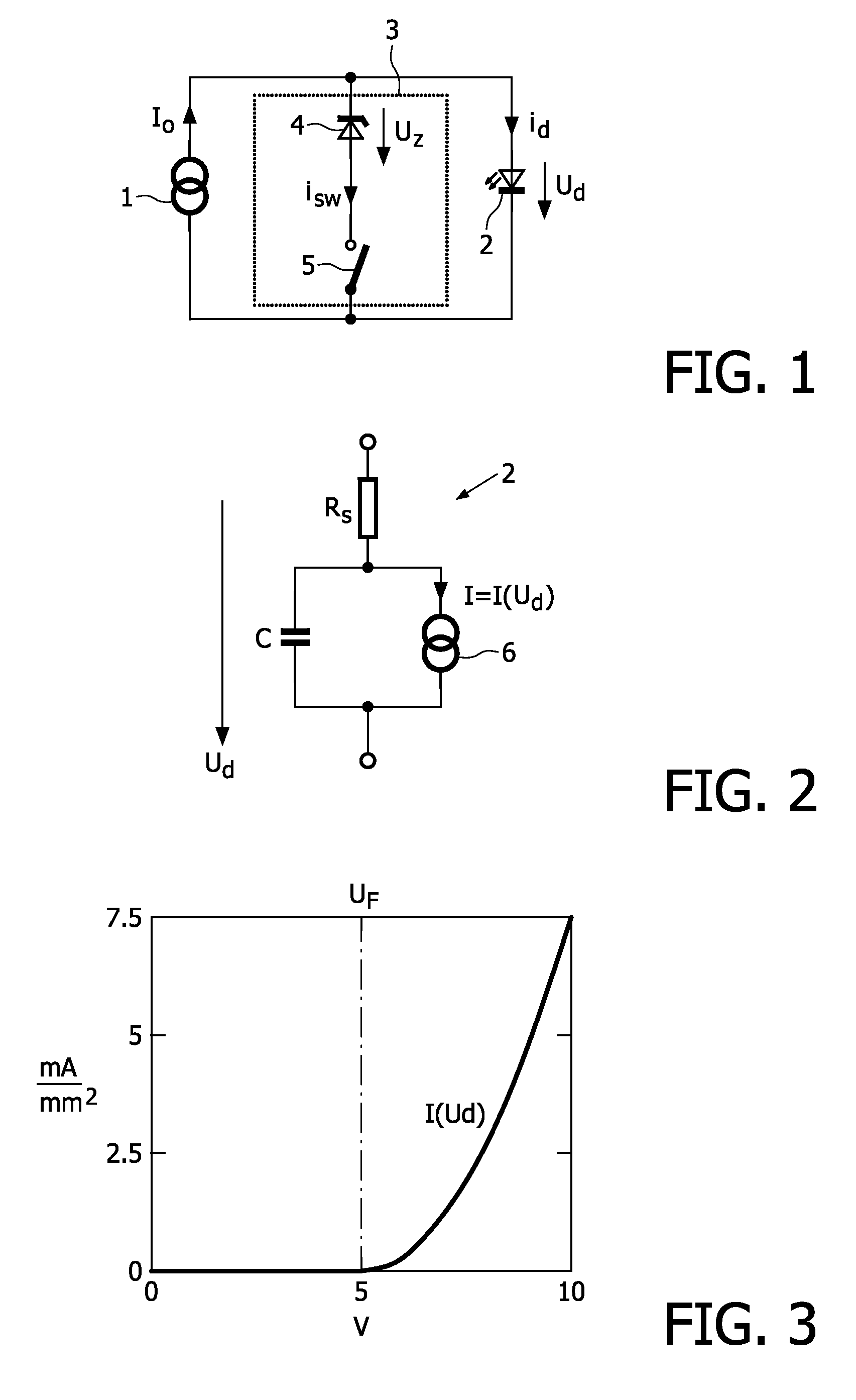
[0032]When the current I0 is applied to the circuit-arrangement and the switch 5 is in the open state, as shown, the current charges the intrinsic capacitance C of the OLED 2. When the intrinsic capacitance C is ful...


PUM


Abstract

To achieve high modulation frequencies when modulating an LED, a circuit-arrangement for modulating at least one LED comprises a modulation-circuit (3) parallel to the LED, wherein the modulation-circuit (3) comprises in a series connection a switching device and a threshold device. In a method for operating an LED, the LED is modulated by alternating the switching device between a closed state and an open state.

Description

FIELD OF THE INVENTION[0001]The present invention relates to a circuit-arrangement for modulating an LED, a system for modulating a plurality of LEDs and a method for operating an LED.[0002]LEDs are used today in many applications, due to their low power consumption and long lifetime. Accordingly, several types of driver-circuits are available to operate such an LED.BACKGROUND OF THE INVENTION[0003]For some applications, it is necessary to enable a modulation of the LED. A solution to this problem is shown in the prior art. U.S. Pat. No. 5,959,413 discloses in FIG. 8 a series arrangement of three LEDs, driven by a single current source 192. Switches 186, 188, 190 are arranged parallel to the respective LED, which enable an alternate current path, so that the respective LED can be short-circuited and thus can be switched off and on.[0004]Although the shown approach ensures a constant current through each LED, a disadvantage of this circuit is that a high frequency modulation of the L...

Claims


Application Information

Patent Timeline
Patent Type & Authority Applications(United States)
IPC IPC(8): H05B41/36H01L33/00H05B44/00
CPCH04B10/502H05B33/0803H05B33/0818H05B33/0824H05B33/083Y02B20/346H05B45/48H05B45/44H05B45/30Y02B20/30
Inventor HENTE, DIRKSAUERLANDER, GEORG
Owner SIGNIFY HLDG BV
Why Eureka
Try Eureka