Transformer unit, and power converting device

a transformer unit and transformer technology, applied in transformer/inductance details, solid-state devices, inductances, etc., can solve the problems of increasing the size of the circuit, difficult to reduce cost and size, and increasing the temperature dependence of the coupling constant, so as to reduce the superposition of external magnetic flux, reduce the cost and size of the power electronic device, and reduce the effect of cost and siz

Inactive Publication Date: 2008-10-30
FUJI ELECTRIC CO LTD
View PDF11 Cites 52 Cited by
  • Summary
  • Abstract
  • Description
  • Claims
  • Application Information

AI Technical Summary

Benefits of technology

[0028]As a result, the secondary winding is equipped with the windings so that it can cancel the electromotive forces due to the external magnetic fluxes interlinking the secondary winding, thereby to reduce the superposition of the external magnetic fluxes as noise on the secondary winding, without using any magnetic core. As a result, the signal transfer can be made by avoiding the risk, as might otherwise invite the malfunction, while insulating the control circuit side and the switching element side electrically, and the power electronic device can be reduced in cost and

Problems solved by technology

However, the method using a transformer with a core as a signal transmitting insulated transformer has problems in that a temperature dependency of a coupling constant is increased by the influence of the temperature characteristics of the permeability of a magnetic member, and that it is difficult to reduce cost and size.
Further, the PWM signal itself cannot be directly sent through the transf

Method used


Image

  • Transformer unit, and power converting device
  • Transformer unit, and power converting device
  • Transformer unit, and power converting device

Examples


first embodiment

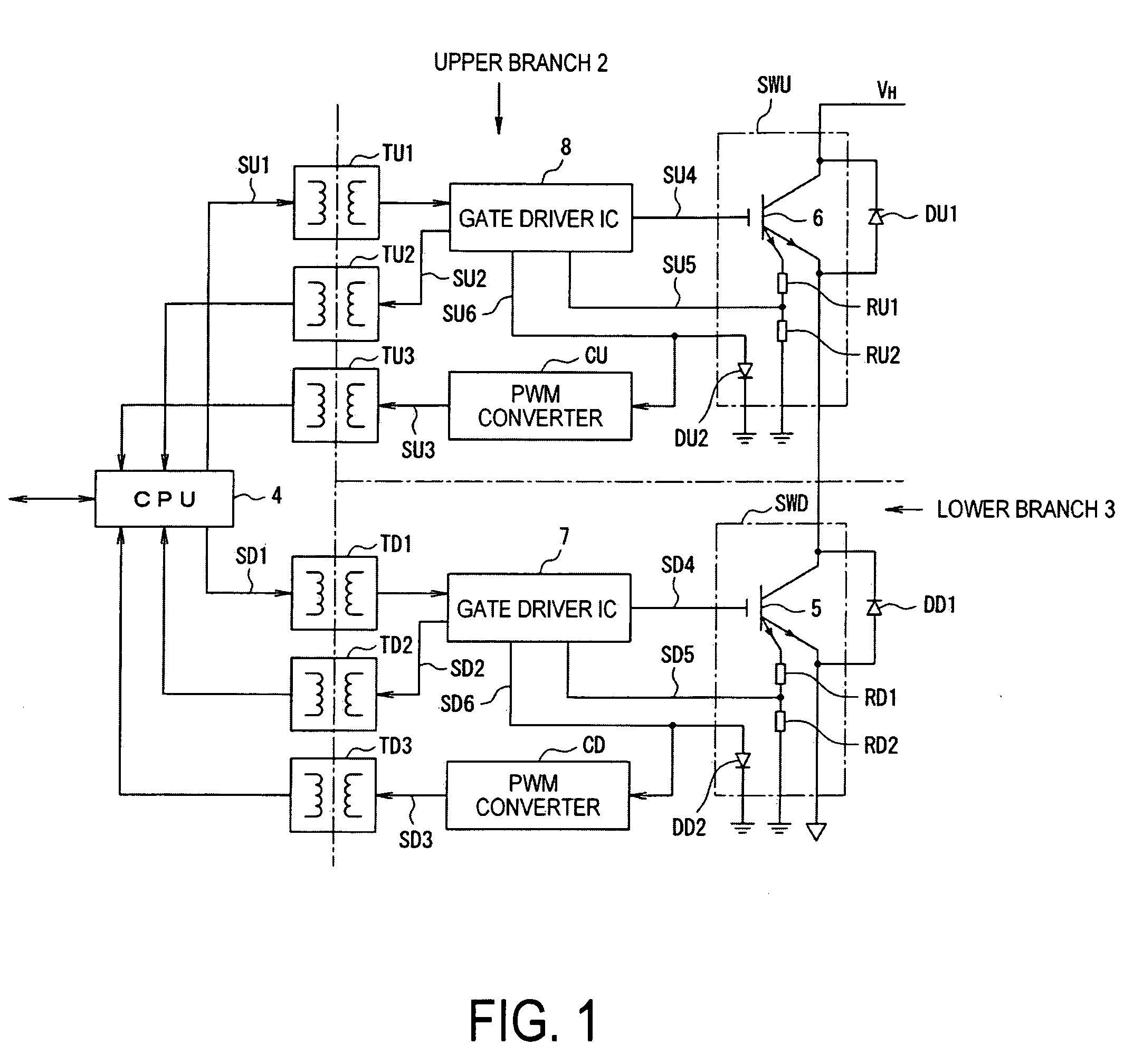
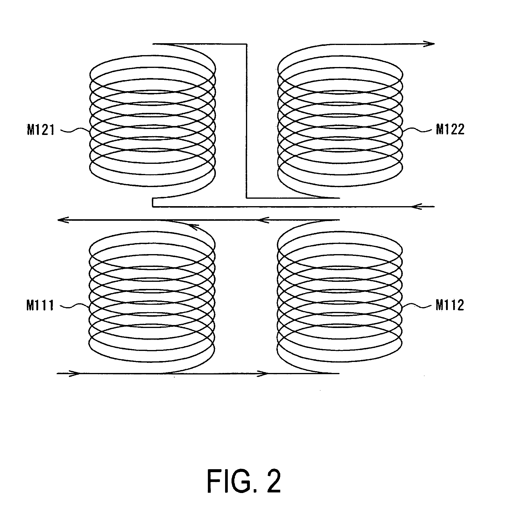
[0065]FIG. 2 is an external view of the air-core type insulated transformer according to the invention. In FIG. 2, the air-core type insulated transformers TU1 to TU3 and TD1 to TD3 of FIG. 1 can be equipped with a first winding M111 and a second winding M112 of the primary winding for playing the role of the sending side and with a first winding M121 and a second winding M122 of the secondary winding for playing the role of the receiving side. Here, the first winding M111 and the second winding M112 of the primary winding can be so individually set in their winding directions that the directions of the magnetic fields generated by the exciting current may be contrary to each other, and can be connected in parallel. The first winding M121 and the second winding M122 of the secondary winding can be so individually set in their winding directions that the electromotive forces generated by the external magnetic fluxes may cancel each other, and can be so connected in series as to enhan...

second embodiment

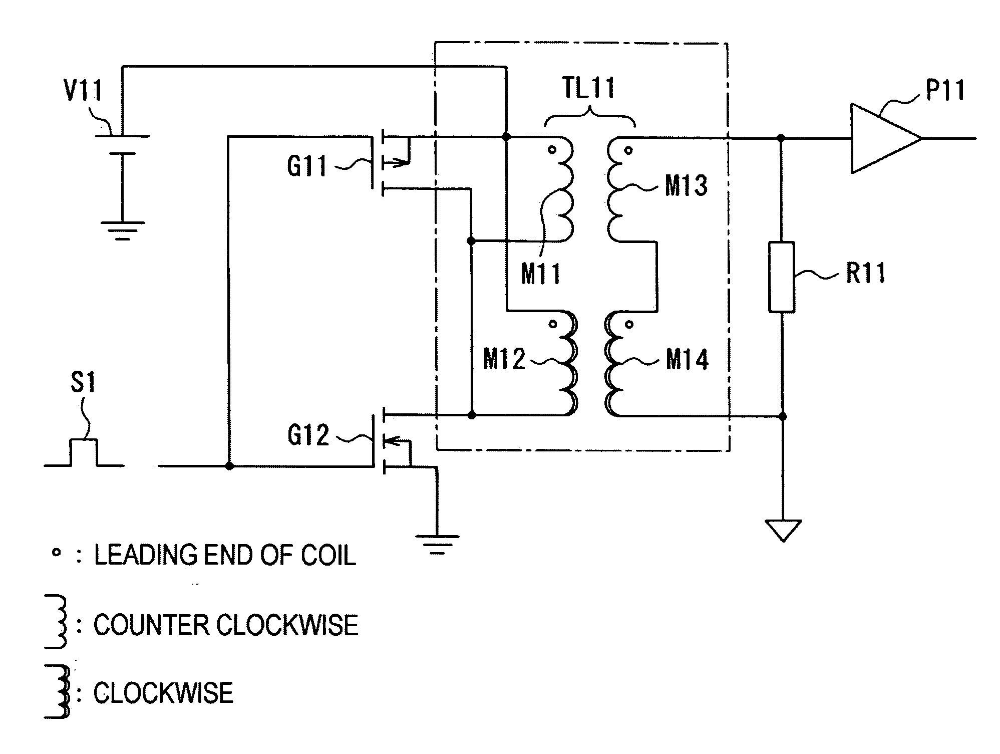
[0080]FIG. 11 is a diagram showing a circuit constitution of a transformer unit according to the invention. In FIG. 11, field effect type transistors G11 and G12 are connected in series. The field effect type transistor G11 has its source connected with a power source V11, and the field effect type transistor G12 has its source grounded to the earth. An air-core type insulated transformer TL11 is equipped at its primary winding with a first winding M11 and a second winding M12 of different winding directions. The leading end of the first winding M11 of the primary winding and the leading end of the second winding M12 of the primary winding are connected with each other, and the trailing end of the first winding M11 of the primary winding and the trailing end of the second winding M12 of the primary winding are connected with each other. In the example of FIG. 11, the windings M11 and M13 are counter-clockwise, and the windings M12 and M14 are clockwise. The winding directions are in...

third embodiment

[0086]FIG. 12 is a diagram showing a circuit constitution of a transformer unit according to the invention. In FIG. 12, field effect type transistors G21 and G22 are connected in series. The field effect type transistor G21 has its source connected with a power source V21, and the field effect type transistor G22 has its source grounded to the earth. Further, the air-core type insulated transformer TL21 is equipped at its primary winding with a first winding M21 and a second winding M22 of identical winding directions. The leading end of the first winding M21 of the primary winding and the trailing end of the second winding M22 of the primary winding are connected with each other, and the trailing end of the first winding M21 of the primary winding and the leading end of the second winding M22 of the primary winding are connected with each other.

[0087]the air-core type insulated transformer TL21 is equipped at its secondary winding with a first winding M23 and a second winding M24 o...


PUM


Abstract

A transformer unit and a power converting device, which lessen the influence of noise caused by an external magnetic flux, while reducing the temperature dependency of a coupling coefficient, and which transfer signals while insulating a low-voltage and a high-voltage side electrically. Air-core type insulated transformers have a first and second winding of a primary winding as a sending side and a first and second winding of a secondary winding as a receiving side. The windings of the primary winding are connected in parallel and are wound so that the directions of magnetic fields generated by an exciting current oppose each other. The windings of the secondary winding are wound so that electromotive forces to be generated by an external magnetic flux cancel each other, and are connected in series so as to raise the electromotive forces by a signal magnetic flux generated by the primary winding.

Description

BACKGROUND OF THE INVENTION[0001]1. Field of the Invention[0002]The present invention relates to a transformer unit and a power converting device, and to a method for transmitting signals to switching elements through an air-core type insulated transformer.[0003]2. Description of Related Art[0004]Of recent years, in order to enhance the efficiency of and to reduce the energy consumption of an electric vehicle, a step-up / step-down converter and an inverter are mounted on a drive system for an electric motor to generate driving power. FIG. 19 is a block diagram of a vehicle driving system using a step-up / step-down converter of the related art. In FIG. 19, the vehicle driving system is equipped with: a power source 101 for feeding electric power to a set-up / set-down converter 102; the set-up / set-down converter 102 for setting a voltage up / down; an inverter 103 for converting the voltage outputted from the set-up / set-down converter 102 into a three-phase voltage; and an electric motor 1...

Claims


Application Information

Patent Timeline
IPC IPC(8): H01F27/34
CPCH01F17/0013H01F17/02H01F27/2804H02M3/33569H01L2224/48137H01L2924/13055H01L2924/1305H01L2924/00H01F2027/2809H02M3/33571
Inventor YOSHIMURA, HIROYUKISUGIMOTO, MASATOSHI
Owner FUJI ELECTRIC CO LTD
Why Eureka
Try Eureka