
Method & Apparatus for Demodulating an Optical Differential Phase-Shift Keying Signal

Active Publication Date: 2008-10-30
XIEON NETWORKS SARL
View PDF3 Cites 7 Cited by
  • Summary
  • Abstract
  • Description
  • Claims
  • Application Information

AI Technical Summary

Benefits of technology

[0002]The reasons for this renewed interest include, amongst others, the relatively good receiver sensitivity that can be achieved using a DPSK network. DPSK also features an independency of the decision threshold from power fluctuations and is tolerant to optical filtering. In addition, DPSK boasts a robustness to nonlinearities, which make binary DPSK (DBPSK) particularly suited for long-haul applications and quaternary DPSK (DQPSK), DQPSK is particularly robust to fiber dispersion effects.
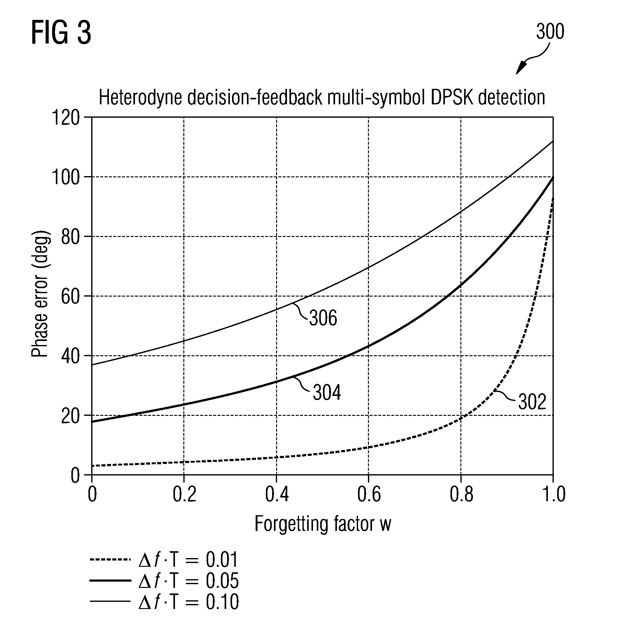
[0021]The essence of the method described by Lieb consists in replacing the previous symbol y(n−1) by the sum of y(n−1) and a term that depends recursively on the past received symbols. The factor exp[jc(n−1)] rotates the previous reference symbol Z(n−2) to align it with y(n−1), whereas the forgetting factor w limits the memory of the system by attenuating the effect of the old symbols respect to the last one. For w=0, we have the conventional heterodyne DPSK detection. As w increases, a longer averaging takes places and a better performance is achieved. For w=1 the detector has infinite memory and approaches the performance of a homodyne demodulator.
[0027]What is lacking in the art is the ability to achieve DPSK demodulation of an optical signal with high accuracy that does not suffer from the dilatory effects of frequency offset between the signal carrier and the local oscillator. What is needed is a DPSK demodulator that achieves high accuracy for an optics solution, yet is inexpensive and reduced in complexity.SUMMARY OF THE INVENTION

Problems solved by technology

However, the homodyne technique is relatively complex, and is in practice not employed.
However, in the presence of phase noise the penalty increases significantly.
Heterodyne demodulation does not seem to suit the peculiarities of optical transmission systems.
261-263, that the laser phase noise represents a critical issue.
On the other hand, XPM-induced phase noise can have a disastrous impact when installed OOK systems are upgraded with phase-shift keying modulation formats as illustrated by either M. Rohde, C. Casper, N. Heimes, M. Konitzer, E.-J.
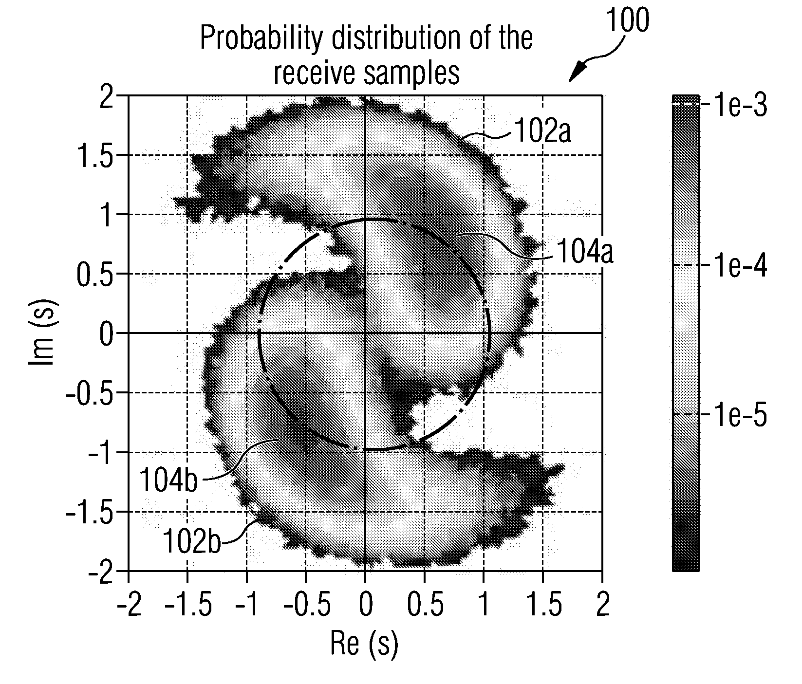
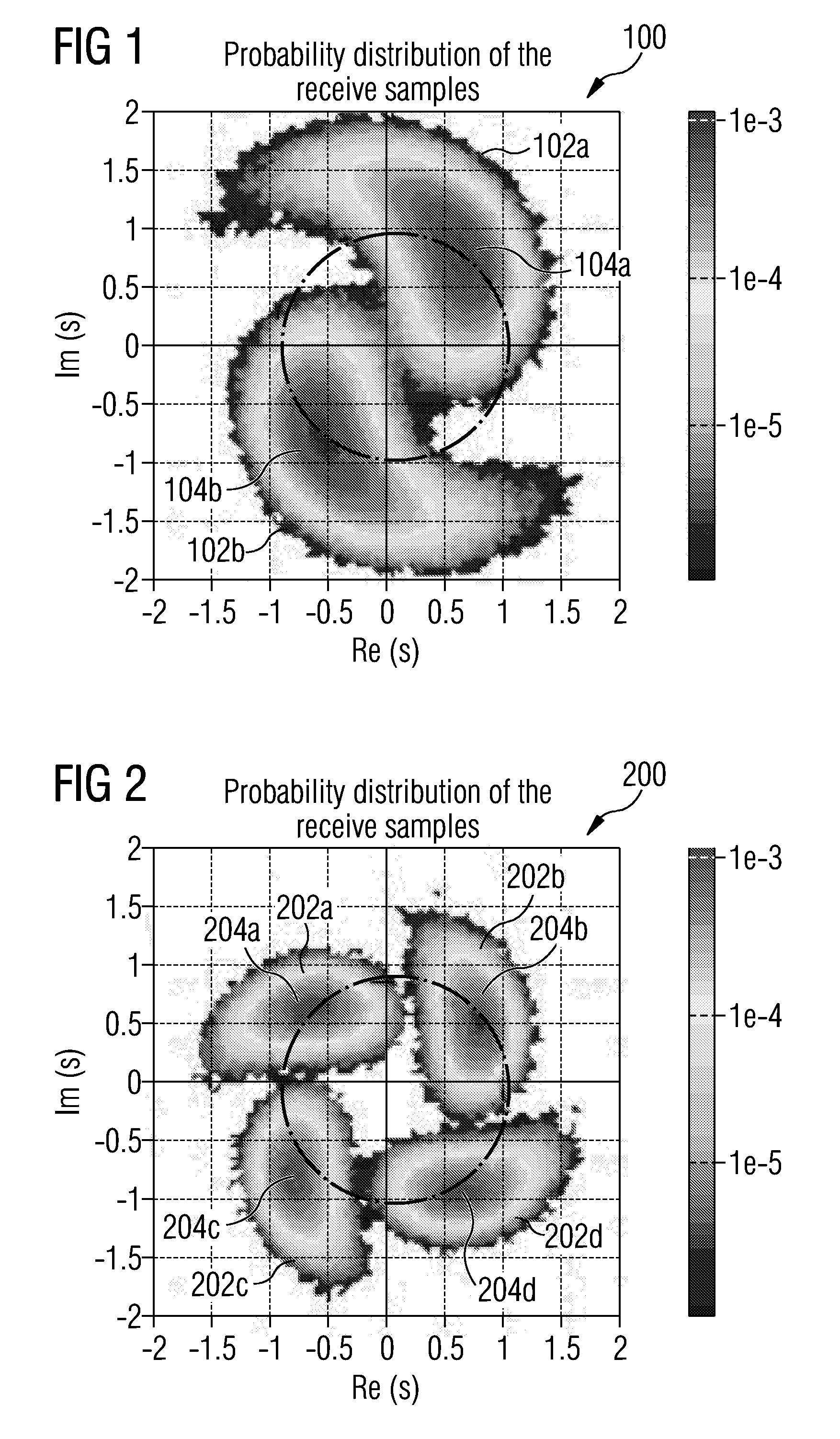
If the clouds are not well-separated, the error probability will be high.
However, these methods are ineffective against other types of phase noise than self-phase nonlinear phase noise as cross-phase nonlinear phase noise or XPM-induced phase noise, which do not exhibit a correlation between received power and phase rotation.
Moreover they cannot reduce the inherent performance penalty of a DQPSK interferometric discriminator and therefore do not address the whole problem discussed by Gnauck.
Unfortunately, these techniques are based on a heterodyne structure and, therefore, imply a local oscillator with polarization control.
Further, and although they can efficiently compensate random phase noise, by averaging it out, they suffer from a frequency offset between the signal carrier and the local oscillator.
This makes old symbols useless, if not harmful, for the recovery of a stable phase reference, thereby limiting the efficiency of the approach itself.
In order to avoid this effect, the frequency offset between local oscillator and signal carrier must be controlled through a suitable circuit, which leads to additional complexity.
However, frequency offset, such as that generated in wireless systems such as Lieb's, results in unsatisfactory phase error in optical solutions.
For optical systems, such a phase error is intolerable.
It is apparent, therefore, that Lieb's solution is insufficient for optical solutions.
What is lacking in the art is the ability to achieve DPSK demodulation of an optical signal with high accuracy that does not suffer from the dilatory effects of frequency offset between the signal carrier and the local oscillator.

Method used


Image

  • Method & Apparatus for Demodulating an Optical Differential Phase-Shift Keying Signal
  • Method & Apparatus for Demodulating an Optical Differential Phase-Shift Keying Signal
  • Method & Apparatus for Demodulating an Optical Differential Phase-Shift Keying Signal

Examples


Embodiment Construction

[0035]According to the technique of the proposed invention, the disturbance attributed to frequency offset is avoided whilst achieving excellent performance characteristics. This is achieved in the present invention by applying a self-homodyne receiver for receiving the optical signal. Since self-homodyne receivers are not dependent on a local oscillator, the problem of frequency offset is avoided. In order to account for this new receiver applied at the front end of an optics demodulator, a unique post-processing apparatus and process was needed to be invented. That process in essence performs a comparison on the decision using a recursion technique, thereby producing an improved decision variable x(nT).

[0036]An exemplary implementation 400 of the invention shall now be described with reference to FIG. 4. The received signal r(t) is split into two portions and sent through an optical receiver, the self-homodyne receiver of the present invention. In one aspect of the invention, the ...


PUM


Abstract

Demodulating an optical Differential Phase-Shift Keying (DPSK) signal is accomplished using a self-homodyne receiver for receiving the optical signal. A converter converts the optical signal received by the self-homodyne receiver into a representative electrical signal. A processor that processes the representative electrical signal using decision feedback multi-symbol detection in order to obtain a decision variable that indicates a differential phase-shift in the optical signal.

Description

[0001]Differential phase-shift keying (DPSK) has recently been met with a rekindled interest from the optical community. A large number of experimental reports and theoretical works have been recently released. See, e.g., A. H. Gnauck and P. J. Winzer in their article, “Phase-shift-keyed transmission”, OFC 2004, Feb. 22-27, 2004, Los Angeles, Calif., USA, Tutorial TuF5.[0002]The reasons for this renewed interest include, amongst others, the relatively good receiver sensitivity that can be achieved using a DPSK network. DPSK also features an independency of the decision threshold from power fluctuations and is tolerant to optical filtering. In addition, DPSK boasts a robustness to nonlinearities, which make binary DPSK (DBPSK) particularly suited for long-haul applications and quaternary DPSK (DQPSK), DQPSK is particularly robust to fiber dispersion effects.[0003]In brief, Phase-shift keying (PSK) is a method of digital communication in which the phase of a transmitted signal is vari...

Claims


Application Information

Patent Timeline
IPC IPC(8): H04B10/06H04L27/22H04B10/66
CPCH04B10/66H04L27/223
Inventor CALABRO, STEFANO
Owner XIEON NETWORKS SARL
Learn More