Solid-state chemical current source and a method for increasing a discharge power

a chemical current source and solid-state technology, applied in the field of electric engineering, can solve the problems of pyrotechnic heaters and systems for their ignition, high internal resistance at ambient temperatures, and complicating the design of current sources, so as to prolong the high-power discharge time, reduce heat loss of heated galvanic cells, and reduce heat loss

Inactive Publication Date: 2008-10-30
THE POTANIN INST
View PDF8 Cites 5 Cited by
  • Summary
  • Abstract
  • Description
  • Claims
  • Application Information

AI Technical Summary

Benefits of technology

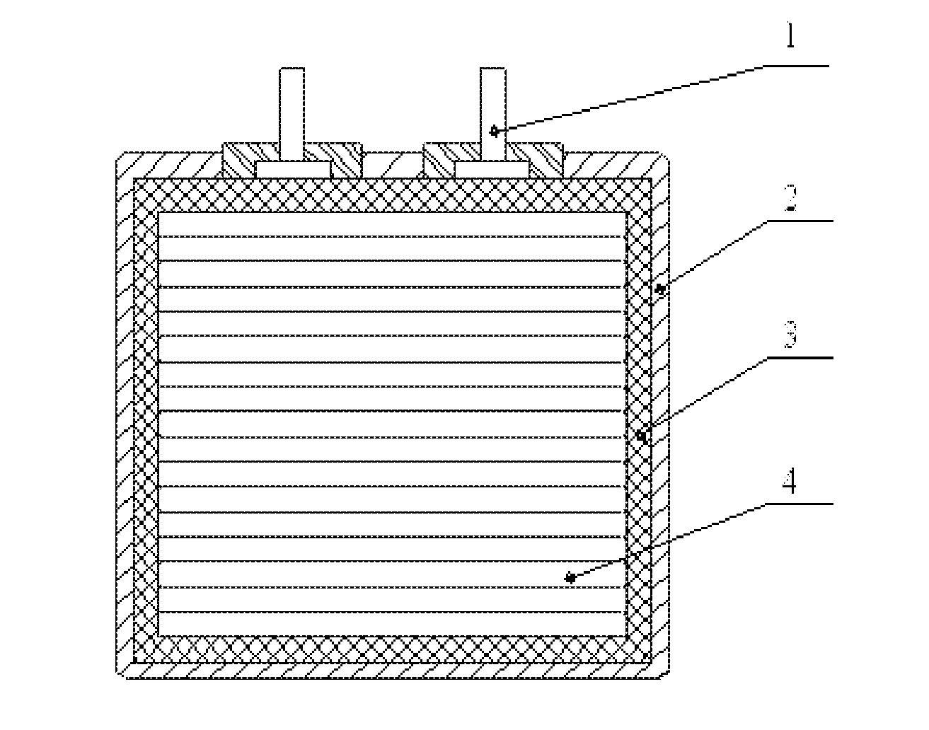
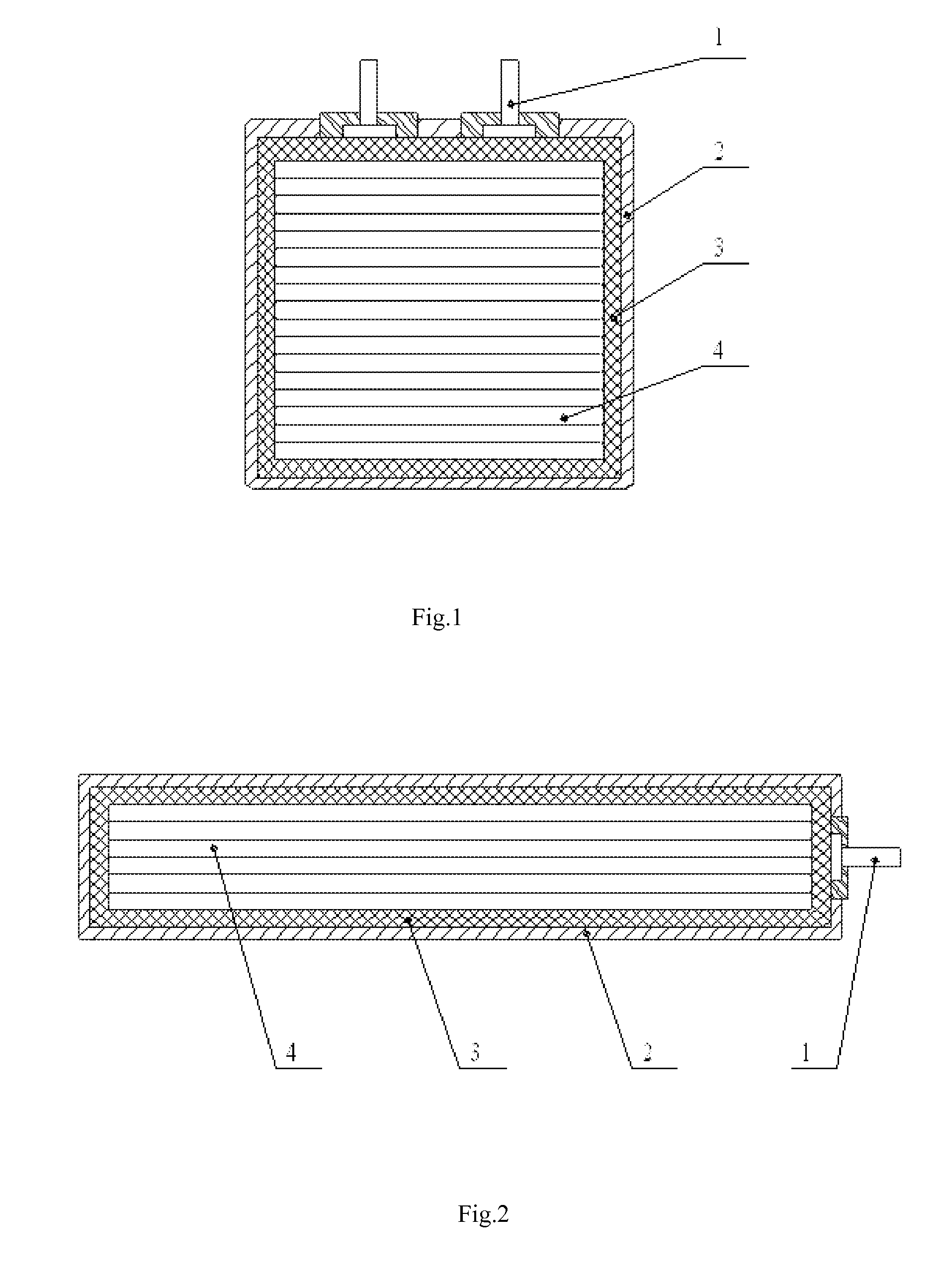
[0037]4. In order to prolong the high power discharge time the heat insulation is arranged inside and / or outside the battery's body. The porous heat-insulated materials consisting of alumina, or silicon oxide, or asbestos, or glass fiber, or compositions, containing the listed, or / and heat shields reducing heat losses of the heated galvanic cells, or / and some other devices, which are effective against heat loss are used as the heat insulation. At that the heat insulation reducing heat losses of the heated galvanic cells can perform the function of and be used as the battery's body.

Problems solved by technology

The drawback of this current source is very high internal resistance at ambient temperatures (for example, the internal resistance per unit surface of the real galvanic cell exhibiting the specific ionic conductivity of 1*10−4 Ohm−1 cm−1 at 25° C. and the electrolyte's thickness of 0.2 mm is 200 Ohm / cm2).
These disadvantages are also typical for other solid-state current sources.
The thermal current sources have the following drawbacks:They are only primary batteries and can not operate as secondary (storage) batteries, that is why a range of their application is limited.The pyrotechnic heaters and systems for their ignition complicate the current source's design, which is not uniform.

Method used


Image

  • Solid-state chemical current source and a method for increasing a discharge power
  • Solid-state chemical current source and a method for increasing a discharge power

Examples


Embodiment Construction

[0043]Principle of operation of the present invention consists of the following:

[0044]The current leading-out wires are connected with an outside load and the current source containing the high-power galvanic cells, based on the solid ion conductors starts to produce electric current. At that, the ion conductor-based solid galvanic cells are heated up due to the ion transport in the solid ion conductors and perform an additional function of heating elements. The solid-state galvanic cells based on the solid ion conductors perform the function of the heating elements very efficiently because during heating the ionic conductivity of the solid-state ion conductors and a rate of the current-producing electrode reactions increase, and as a result the galvanic cells' internal resistance decreases and a power of the discharge current increases. A reciprocal resistance of the solid ion conductor-based galvanic cell increases exponentially with the temperature growth because in general in th...


PUM

PropertyMeasurementUnit
thicknessaaaaaaaaaa
temperaturesaaaaaaaaaa
specific ionic conductivityaaaaaaaaaa

Abstract

The invention relates to a solid-state chemical current source and to a method for increasing a discharge power thereof. The inventive current source can be used in electrochemical engineering, in particular for primary and secondary solid-state chemical power sources, which are based on solid ion conductors and exhibit a high discharge power and for a method for increasing the said discharge power. The solid-state chemical current source comprises a body provided with current leading-out wires and solid-state galvanic cells which are arranged therein, are connected to the current leading-out wires, are based on solid ion conductors and perform the function of heating elements. A heat insulation for reducing heat losses of the heated galvanic cells is arranged inside and\or outside the body. The inventive method for increasing the discharge power of the solid-state chemical current source by heating it consists in using the heat produced by the electric current flowing through the galvanic cells and in maintaining the hot state of the said galvanic cells during the discharge. The said invention makes it possible to obtain a solid-state chemical current source exhibiting a high discharge power, a low self-discharge (about 1-3% per year), a long-term power storage and to increase energy characteristics in such a way that they are equal to or greater than 600 Watt-hour/dm3.

Description

RELATED APPLICATIONS[0001]This application is a Continuation of PCT application serial number PCT / RU2006 / 000711 filed on Dec. 28, 2006, which in turn claims priority to Russian Application No. RU 2006100605 filed on Jan. 10, 2006, both of which are incorporated herein by reference in their entirety.FIELD OF THE INVENTION[0002]The claimed invention relates to the electrical engineering area, in particular to chemical current source both the primary and the secondary (storage batteries) exhibiting high discharge power.[0003]The invention can be of interest in electrical engineering as well as in other engineering areas that demand safe high power-intensive current sources with low self-discharge and high discharge power, namely electric vehicles, telecommunication systems, portable computers, etc.[0004]The present invention refers to a structure of high power-intensive and safe solid-state current sources with low self-discharge during storage and run and to a method for increasing a ...

Claims


Application Information

Patent Timeline
Patent Type & Authority Applications(United States)
IPC IPC(8): H01M6/36H01M10/44H01M10/056H01M10/36H01M50/209
CPCH01M2/1061H01M2/1094H01M2/30H01M6/18H01M10/5089H01M10/056H01M10/5006H01M10/5087H01M6/5038H01M10/615H01M10/659H01M10/658Y02E60/10H01M50/209H01M50/24
Inventor POTANIN, ALEKSANDER ARKADIEVICH
Owner THE POTANIN INST
Why Eureka
Try Eureka