Control Device and Method for Multiprocessor

Inactive Publication Date: 2008-10-30
KK TOSHIBA
View PDF11 Cites 28 Cited by
  • Summary
  • Abstract
  • Description
  • Claims
  • Application Information

AI Technical Summary

Benefits of technology

[0018]A multiprocessor control device according to an example of the invention comprises a selection unit which, on the basis of an execution schedule for a plurality of tasks to be allocated to any one of a plurality of processor elements, selects, for each of the plurality of processor elements, any one of a normal mode used in a task execution time, a first mode which is used when a task is not executed an

Problems solved by technology

If an application with a low parallelism is executed on a multiprocessor, an idle time during which a large number of processor elements mounted on the chip do not execute processes tends to increase.
In this case, the entire multiprocessor wastes electric power and generates heat, which is a problem.
However, in the case of the information processing device according to the above describ

Method used


Image

  • Control Device and Method for Multiprocessor
  • Control Device and Method for Multiprocessor
  • Control Device and Method for Multiprocessor

Examples


first embodiment

[0045]In a first embodiment of the invention, a control processor element (control unit) which schedules tasks and switches between a normal mode, a Rest mode, and a Sleep mode for each of processor elements in a multiprocessor that has a plurality of the processor elements mounted on a single chip will be explained.

[0046]In the first embodiment, an electric power consumption of the processor elements is suppressed in two stages: the Rest mode and Sleep mode.

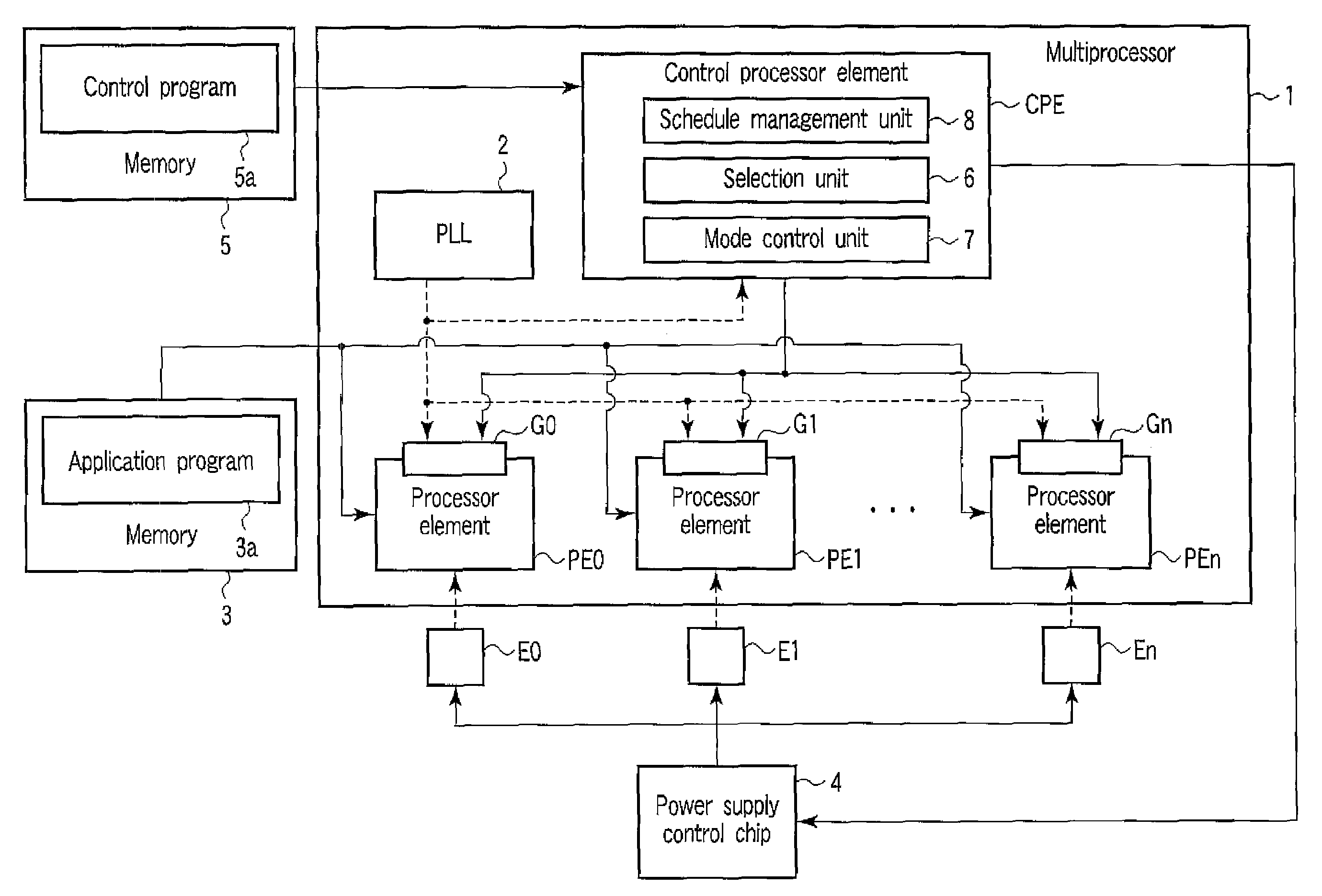
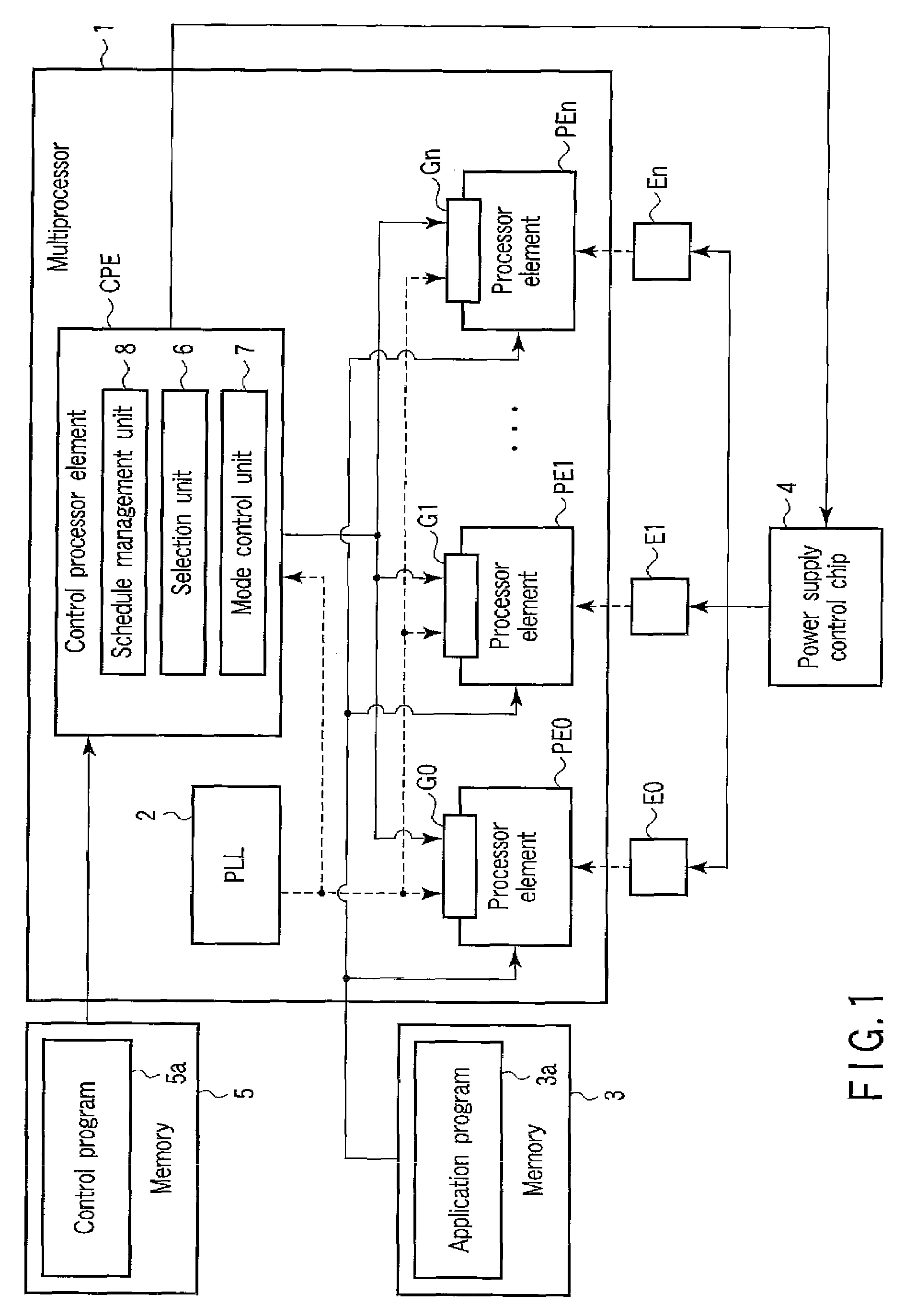
[0047]FIG. 1 is a block diagram showing an example of a multiprocessor which includes a control processor element of the first embodiment.

[0048]A multiprocessor 1 has a plurality of processor elements PE0 to PEn on a single chip. The multiprocessor 1 further includes a PLL (Phase Locked Loop) 2 for generating a clock signal and a control processor element CPE.

[0049]The processor elements PE0 to PEn execute an application program 3a stored in a memory 3.

[0050]The processor elements PE0 to PEn are provided with clock gates G0 to G...

second embodiment

[0117]In a second embodiment of the invention, a modification of the first embodiment will be explained. In the second embodiment, an explanation will be given about a comparison between a case where optimization is performed to concentrate tasks which need not be executed in parallel into a specific processor element and a case where they are not concentrated.

[0118]In the second embodiment, it is assumed that, of 100% of the power consumed in the multiprocessor, 50% is consumed in AC, 40% is consumed in the clock, and 10% is consumed in DC. Here, AC means the power consumed in the operation of a circuit. The clock means the power consumed in the clock supplied to the block. DC means the leakage power of the circuit.

[0119]Moreover, in the second embodiment, suppose the Rest mode is a mode in which the operating frequency is suppressed to ¼ and the Sleep mode is a mode in which the supply of the clock is stopped (clock gating).

[0120]In this case, as illustrated in FIG. 8, in the Rest...

third embodiment

[0131]In a third embodiment of the invention, a control unit for a microprocessor obtained by modifying the first and second embodiments and further dividing the Rest mode into a plurality of modes will be explained.

[0132]FIG. 12 is a block diagram showing an example of a multiprocessor which includes a control processor element of a third embodiment.

[0133]A multiprocessor 11 includes a plurality of processor elements PE0 to PEn r a PLL (Phase Locked Loop) 12, and a control processor element CPE1.

[0134]The processor elements PE0 to PEn execute an application program 3a stored in a memory 3.

[0135]Power supply modules F0 to Fn supply power to the processor elements PE0 to PEn, respectively.

[0136]According to a power supply switching instruction given from the control processor element CPE1, a power supply control chip 13 switches between power supply and power stoppage by the power supply modules F0 to Fn. Moreover, the power supply control chip 13 varies the power supply voltage supp...


PUM


Abstract

An multiprocessor control device according to an example of the invention comprises a selection unit which, on the basis of an execution schedule for tasks to be allocated to any one of processor elements, selects, for each of the processor elements, any one of a normal mode used in a task execution time, a first mode which is used when a task is not executed and in which a power consumption is reduced more than in the normal mode, and a second mode which is used when the task is not executed and which has a greater power consumption reducing effect but a longer mode switching time than the first mode, and a mode control unit which performs control according to the mode selected by the selection unit for each of the processor elements.

Description

CROSS-REFERENCE TO RELATED APPLICATIONS[0001]This application is based upon and claims the benefit of priority from prior Japanese Patent Applications No. 2007-116167, filed Apr. 25, 2007, the entire contents of which are incorporated herein by reference.BACKGROUND OF THE INVENTION[0002]1. Field of the Invention[0003]This invention relates to a multiprocessor control device and a multiprocessor control method for decreasing the electric power consumption in a multiprocessor architecture.[0004]2. Description of the Related Art[0005]In the recent microprocessor, the calculating performance tends to be improved by increasing the number of processor elements rather than increasing the frequency.[0006]In a multiprocessor with a plurality of processor elements, it is desirable that the electric power consumption should be suppressed to low levels.[0007]Processor element monitoring control means capable of controlling the electric power consumption in a plurality of processor elements arra...

Claims


Application Information

Patent Timeline
IPC IPC(8): G06F9/46
CPCG06F1/3203G06F1/3237G06F1/324G06F1/329G06F1/3296G06F9/4893G06F2209/483G06F9/522Y02B60/1217Y02B60/1221Y02B60/1285Y02B60/144G06F9/52Y02D10/00
Inventor YASUKAWA, HIDEKI
Owner KK TOSHIBA
Why Eureka
Try Eureka