Cooling Holes For Gas Turbine Combustor Having A Non-Uniform Diameter Therethrough

Inactive Publication Date: 2008-11-06
GENERAL ELECTRIC CO
View PDF4 Cites 52 Cited by
  • Summary
  • Abstract
  • Description
  • Claims
  • Application Information

AI Technical Summary

Benefits of technology

[0006]In accordance with a first exemplary embodiment of the invention, a gas turbine combustor liner is disclosed as including a shell having a first end adjacent to an upstream end of the combustor and a second end adjacent to a downstream end of the combustor, where the shell also has a hot side, a cold side, and a centerline axis therethrough. A plurality of small, closely-spaced film cooling holes are formed in the shell through which air flows for providing a cooling film along the hot side of the shell. Each cooling hole has a non-uniform diameter as it extends through the shell. In particular, each cooling hole includes a first opening located at the cold side of the shell having a first diameter and a second opening located at the hot side of the shell having a second diameter, wherein the second diameter of the second opening is larger than the first diameter of the first opening. It is preferred that the shape of each cooling hole be substantially frusto-conical.
[0007]In a second exemplary embodiment of the invention, a gas turbine combustor liner is disclosed as including a shell having a first end adjacent to an upstream end of the combustor and a second end adjacent to a downstream end

Problems solved by technology

In particular, each cooling hole includes a first portion having a substantially uniform diam

Method used


Image

  • Cooling Holes For Gas Turbine Combustor Having A Non-Uniform Diameter Therethrough
  • Cooling Holes For Gas Turbine Combustor Having A Non-Uniform Diameter Therethrough
  • Cooling Holes For Gas Turbine Combustor Having A Non-Uniform Diameter Therethrough

Examples


Embodiment Construction

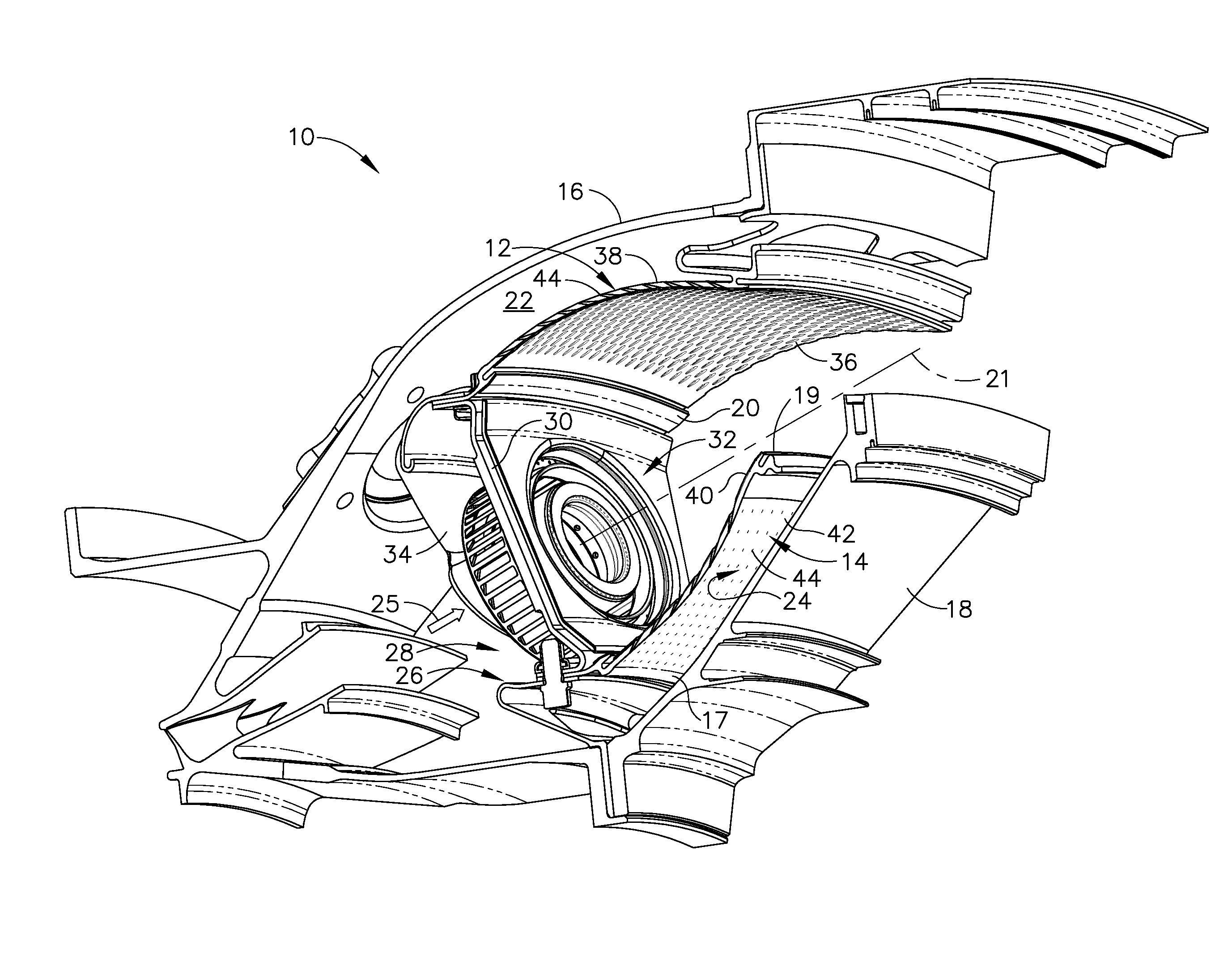
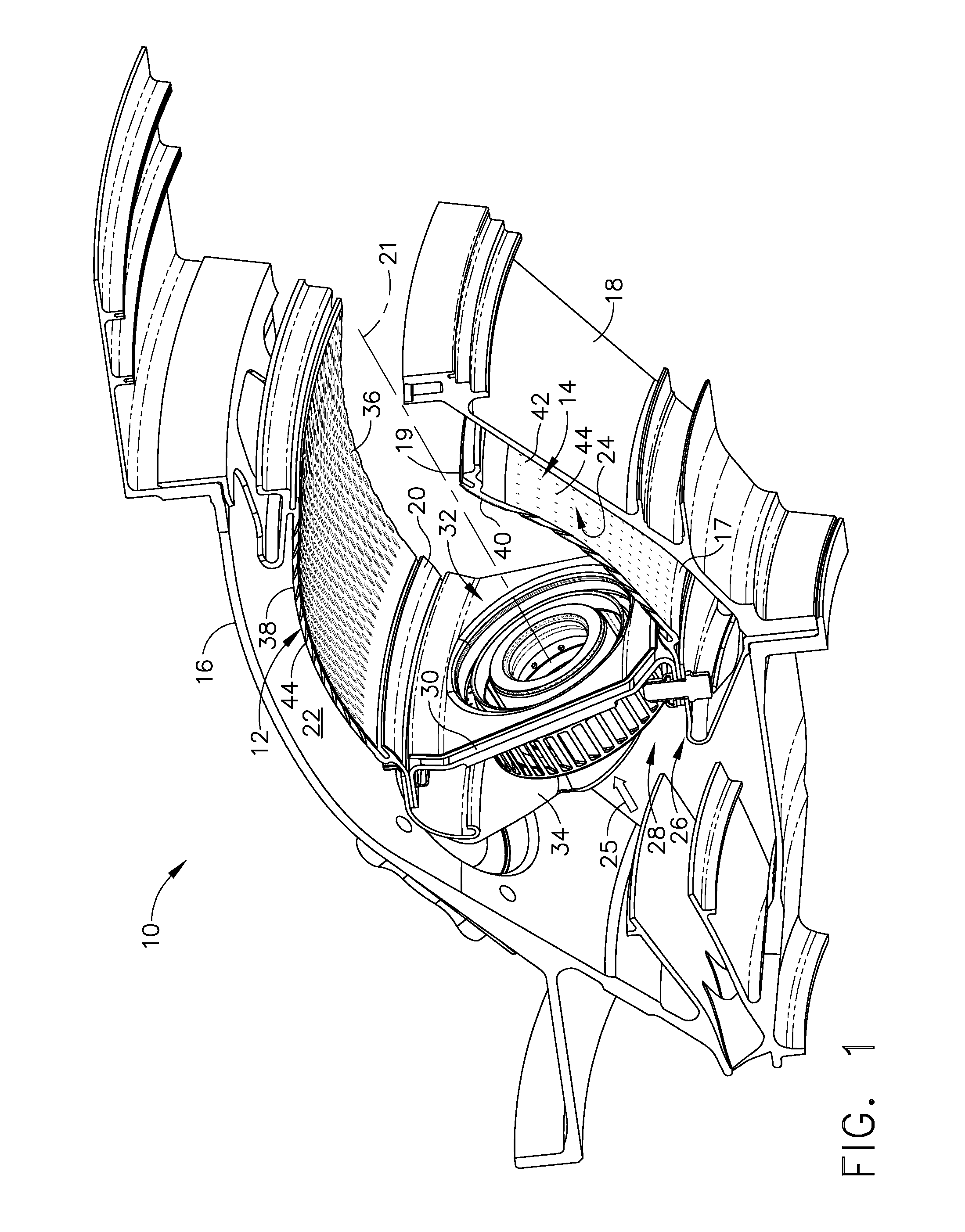
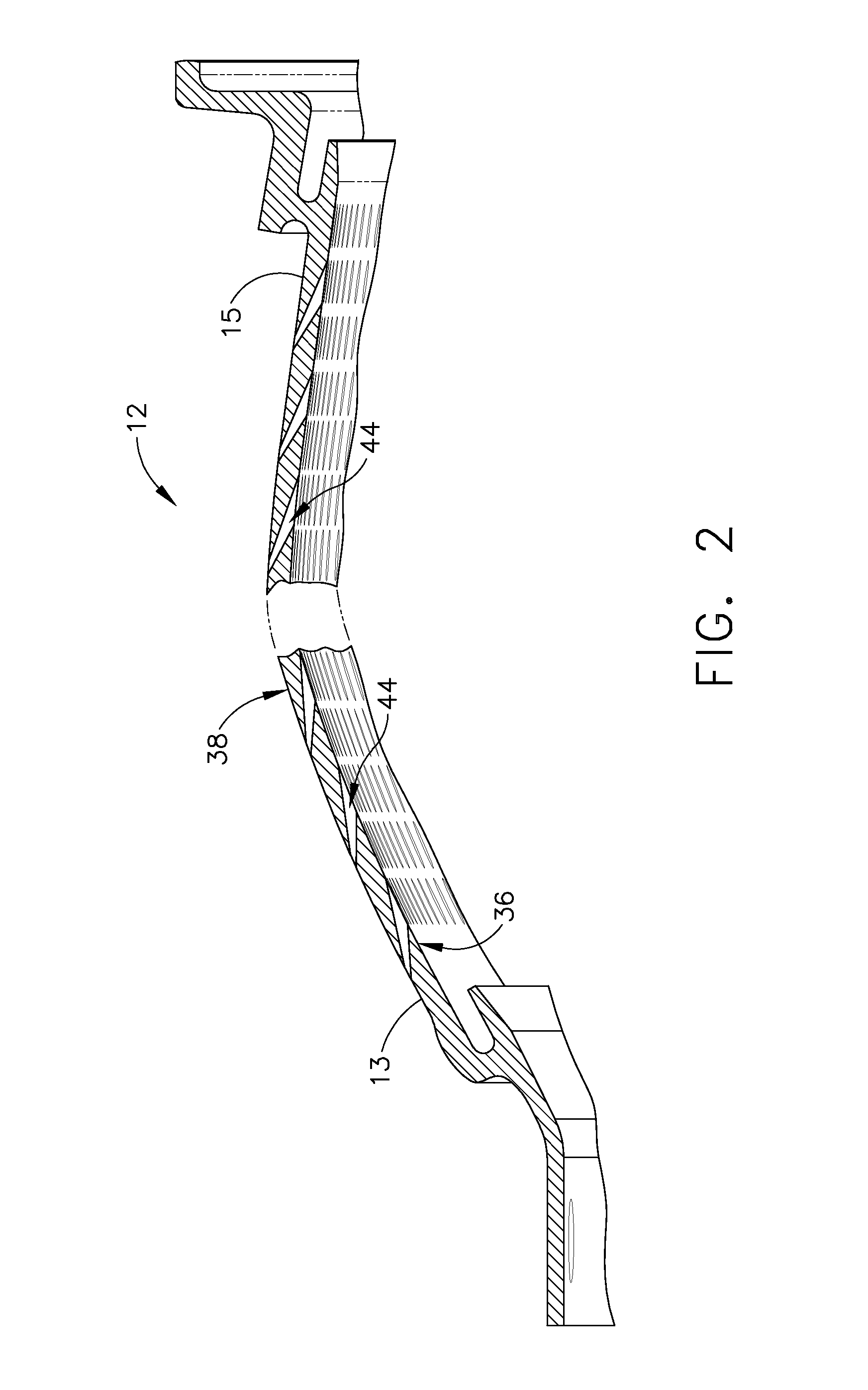
[0018]Referring now to the drawings in detail, wherein identical numerals indicate the same elements throughout the figures, FIG. 1 depicts a combustor 10 of the type suitable for use in a gas turbine engine. Combustor 10 includes an outer liner 12 and an inner liner 14 disposed between an outer combustor casing 16 and an inner combustor casing 18. Outer and inner liners 12 and 14 are radially spaced from each other to define a combustion chamber 20. Outer liner 12 and outer casing 16 form an outer passage 22 therebetween, and inner liner 14 and inner casing 18 form an inner passage 24 therebetween. A cowl assembly 26 is mounted to the upstream ends of outer and inner liners 12 and 14. An annular opening 28 is formed in cowl assembly 26 for the introduction of compressed air into combustor 10. The compressed air is supplied from a compressor (not shown) in a direction generally indicated by arrow 25 of FIG. 1. The compressed air passes principally through annular opening 28 to suppo...


PUM


Abstract

A gas turbine combustor liner, including a shell having a first end adjacent to an upstream end of the combustor and a second end adjacent to a downstream end of the combustor, where the shell also has a hot side, a cold side, and a centerline axis therethrough. A plurality of small, closely-spaced film cooling holes are formed in the shell through which air flows for providing a cooling film along the hot side of the shell. Each cooling hole has a non-uniform diameter as it extends through the shell. In particular, each cooling hole includes a first opening located at the cold side of the shell having a first diameter and a second opening located at the hot side of the shell having a second diameter, wherein the second diameter of the second opening is larger than the first diameter of the first opening. It is preferred that the shape of each cooling hole be substantially frusto-conical.

Description

BACKGROUND OF THE INVENTION[0001]The present invention relates generally to a liner for a gas turbine engine combustor and, in particular, to the configuration of the cooling holes utilized in a multihole cooling scheme for such liner.[0002]Combustor liners are generally used in the combustion section of a gas turbine engine located between the compressor and turbine sections of the engine, although such liners may also be used in the exhaust sections of aircraft engines that employ augmentors. Combustors generally include an exterior casing and an interior combustor where fuel is burned to produce a hot gas at an intensely high temperature (e.g., 3000° F. or even higher). To prevent this intense heat from damaging the combustor case and the surrounding engine before it exits to a turbine, a heat shield or combustor liner is provided in the interior of the combustor.[0003]Various liner designs have been disclosed in the art having different types of cooling schemes. One example of a...

Claims


Application Information

Patent Timeline
IPC IPC(8): F23R3/04
CPCF23R3/002F23R3/06F23R2900/03042Y02T50/675Y02T50/60
Inventor MCMASTERS, MARIE ANNBURRUS, DAVID LOUISHSIAO, GEORGE CHIA-CHUNZHANG, HONGTAOMONGIA, HUKAM CHAND
Owner GENERAL ELECTRIC CO
Why Eureka
Try Eureka