
Method and system for accurate clock synchronization for communication networks

a clock synchronization and communication network technology, applied in the field of clock synchronization between, can solve the problems of inaccurate synchronization method, increased bandwidth consumption, inconvenient deployment, etc., and achieve the effect of minimizing synchronization delay jitter, efficient synchronization, and high accuracy clock synchronization

Inactive Publication Date: 2008-11-06
SAMSUNG ELECTRONICS CO LTD
View PDF5 Cites 86 Cited by
  • Summary
  • Abstract
  • Description
  • Claims
  • Application Information

AI Technical Summary

Benefits of technology

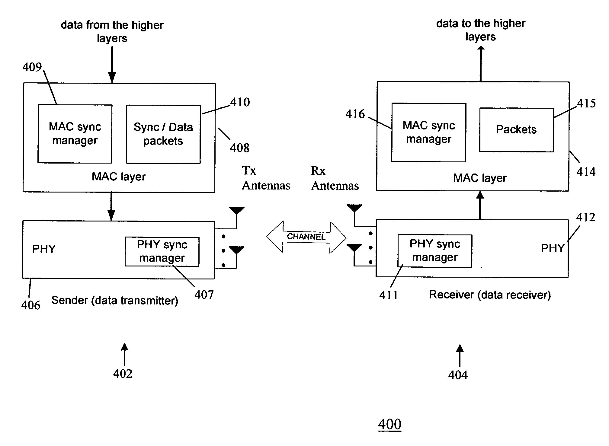
[0007]The present invention provides a high accuracy clock synchronization mechanism for communication between devices in a network. In one embodiment, time synchronization is achieved using broadcast beacons directly at the PHY / MAC layer of a sender (e.g., an AP) and a receiver (e.g., a STA) in a WLAN, to minimize synchronization delay jitter. This provides a more efficient synchronization method than either NTP or SNTP because multiple handshaking information exchanges are avoided. Further, using beacons, the present invention avoids overhead of introducing additional synchronization packets in higher layer synchronization.

Problems solved by technology

However, in WLANs, propagation delay is not the main source of synchronization errors, and extensive handshaking messages may increase bandwidth consumption.
Further, said time synchronization protocols require intensive computation, and consequently, they are inappropriate for deployment in WLANs.
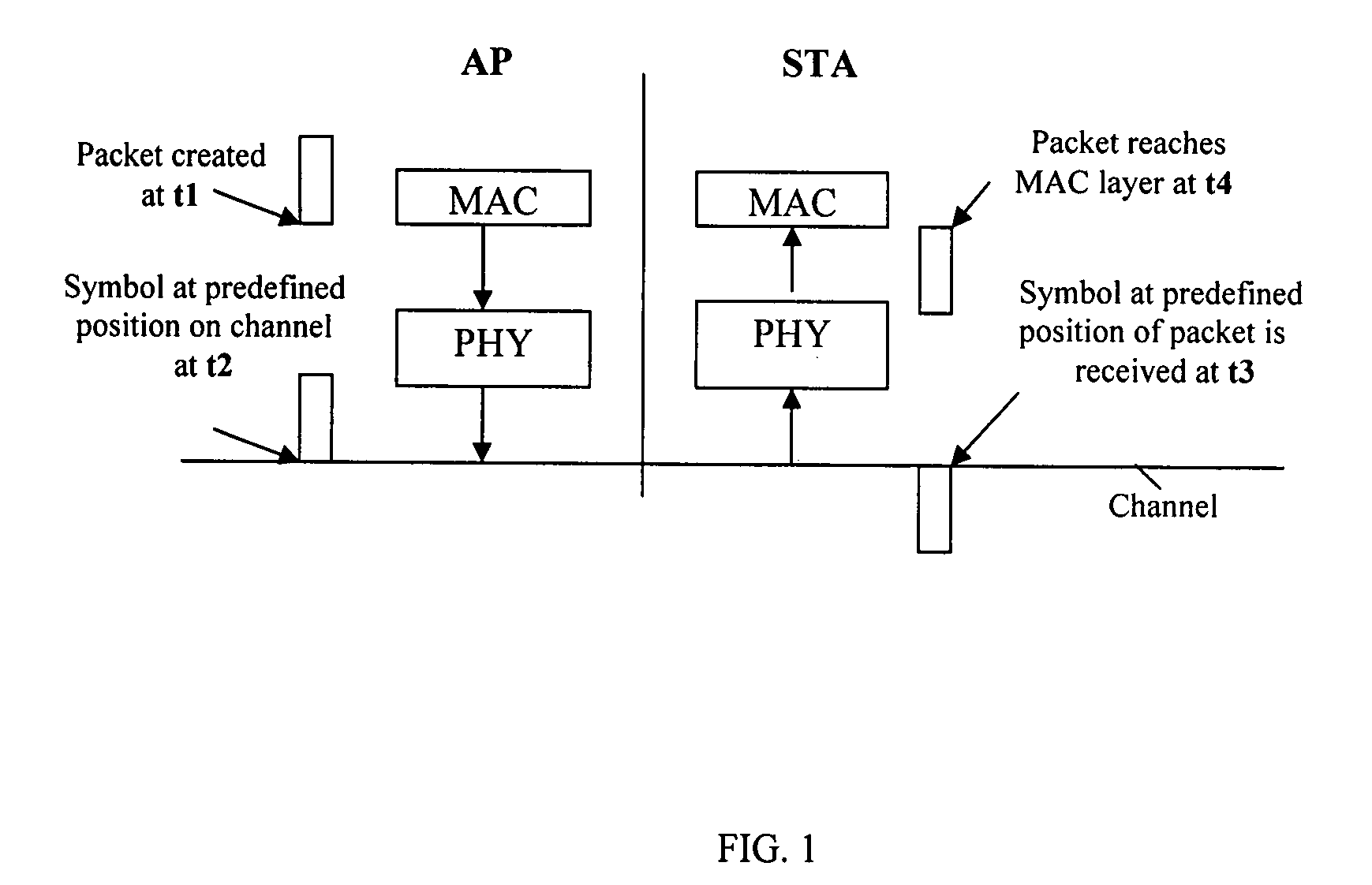
However, this synchronization method is not accurate because it ignores the processing delay of the beacon at the Media Access Control (MAC) and the physical (PHY) layers of both the AP and the STAs, and further ignores the propagation delay through the communication channel between the AP and the STAs.
However, the delay jitter caused by interaction between the higher layer and the MAC layer, and between the MAC layer and the PHY layer is still not eliminated or minimized, leading to time synchronization inaccuracy.

Method used


Image

  • Method and system for accurate clock synchronization for communication networks
  • Method and system for accurate clock synchronization for communication networks
  • Method and system for accurate clock synchronization for communication networks

Examples


Embodiment Construction

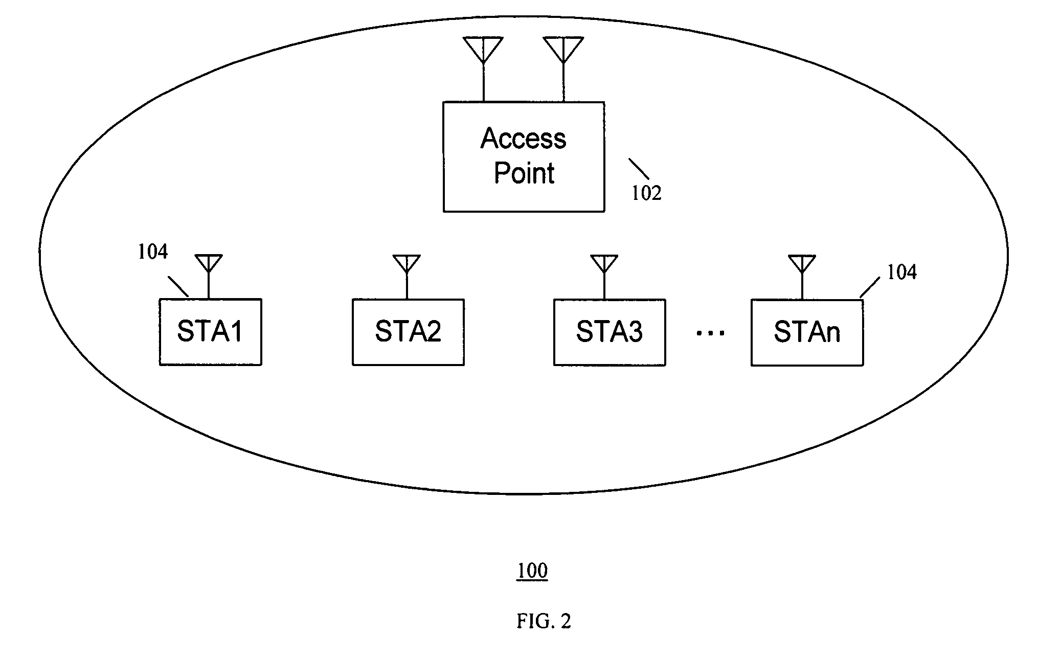
[0020]The present invention provides a high accuracy clock synchronization mechanism for communication between devices in a network. In one embodiment, time synchronization is achieved using broadcast beacons over a wireless channel, directly at the PHY / MAC layers of a sender (e.g., an AP) and a receiver (e.g., a STA) in a WLAN, to minimize synchronization delay jitter.

[0021]The AP and the STA implement a frame structure that is used for data transmission therebetween, using packet transmission in a MAC layer and a physical (PHY) layer. In a typical AP, a MAC layer receives a data packet including payload data, and attaches a MAC header thereto, in order to construct a MAC Protocol Data Unit (MPDU). The MAC header includes information such as a source address (SA) and a destination address (DA). The MPDU is a part of a PHY Service Data Unit (PSDU) and is transferred to a PHY layer in the AP to attach a PHY header (i.e., a PHY preamble) thereto to construct a PHY Protocol Data Unit (...


PUM


Abstract

A high accuracy clock synchronization mechanism between a sender and a receiver in a communication network achieves time synchronization using broadcast beacons, directly at the PHY / MAC layer of the sender and the receiver, to minimize synchronization delay jitter. This provides a more efficient synchronization method than either NTP or SNTP, because multiple handshaking information exchange is avoided. Further, using beacons avoids the overhead of introducing additional synchronization packets in higher layer synchronization.

Description

FIELD OF THE INVENTION[0001]The present invention relates to clock synchronization between communication devices, and in particular to accurate clock synchronization for devices communicating in wireless local area networks (WLANs).BACKGROUND OF THE INVENTION[0002]Time synchronization protocols, such as Network Time Protocol (NTP) and Simple Network Time Protocol (SNTP), have been extensively studied for traditional Internet and distributed systems. These protocols require multiple handshaking information exchanges in order to minimize estimation of the propagation delay error.[0003]However, in WLANs, propagation delay is not the main source of synchronization errors, and extensive handshaking messages may increase bandwidth consumption. Further, said time synchronization protocols require intensive computation, and consequently, they are inappropriate for deployment in WLANs.[0004]The IEEE 802.11 protocol specification provides a simple clock synchronization solution, wherein an ac...

Claims


Application Information

Patent Timeline
IPC IPC(8): H04J3/06
CPCH04W56/0015H04W56/0065H04W92/10H04J3/0697H04J3/0664
Inventor SHAO, HUAI-RONGNGO, CHIU
Owner SAMSUNG ELECTRONICS CO LTD
Learn More