Process for Fabricating Pressure Vessel Liner

a technology for pressure vessels and lines, applied in the field of lines, can solve the problems of shortening the life of the probe, insufficient strength of the vessel liner, etc., and achieve the effects of reducing apparatus costs, preventing deformation, and improving pressure resistance and gas tightness

Inactive Publication Date: 2008-11-06
SHOWA DENKO KK
View PDF4 Cites 21 Cited by
  • Summary
  • Abstract
  • Description
  • Claims
  • Application Information

AI Technical Summary

Benefits of technology

[0033]The pressure liner fabrication process according to par. 2) assures the advantages of the process described in par. 1) more remarkably.
[0034]With the pressure liner fabrication process according to par. 3), the liner components can be prevented from deforming when the probe is placed thereinto. This eliminates the need to use a jig for fixing the liner components or to make the entire apparatus complex in construction, and renders the load to be applied by the probe during joining relatively small to obviate the need to use a large-sized apparatus, consequently entailing a reduced apparatus cost.
[0035]The pressure liner fabrication process according to par. 4) further improves the joint in pressure resistance and gas tightness.
[0036]The pressure liner fabrication process according to par. 5) provides a pressure vessel liner o

Problems solved by technology

1), an insufficient heat input produces internal defects in the joint, rendering the pressure vessel liner to be fabri

Method used


Image

  • Process for Fabricating Pressure Vessel Liner
  • Process for Fabricating Pressure Vessel Liner
  • Process for Fabricating Pressure Vessel Liner

Examples


Embodiment Construction

[0045]An embodiment of the invention will be described below with reference to the drawings.

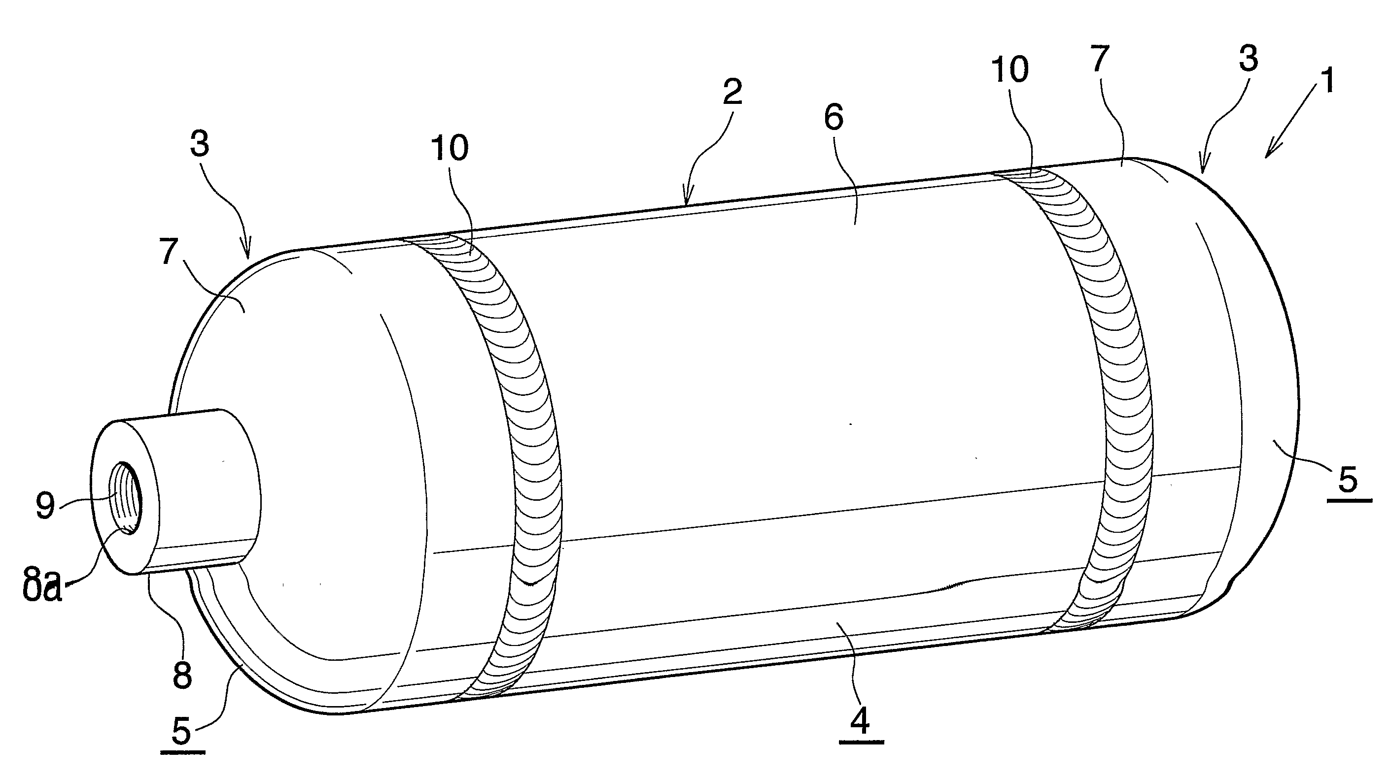
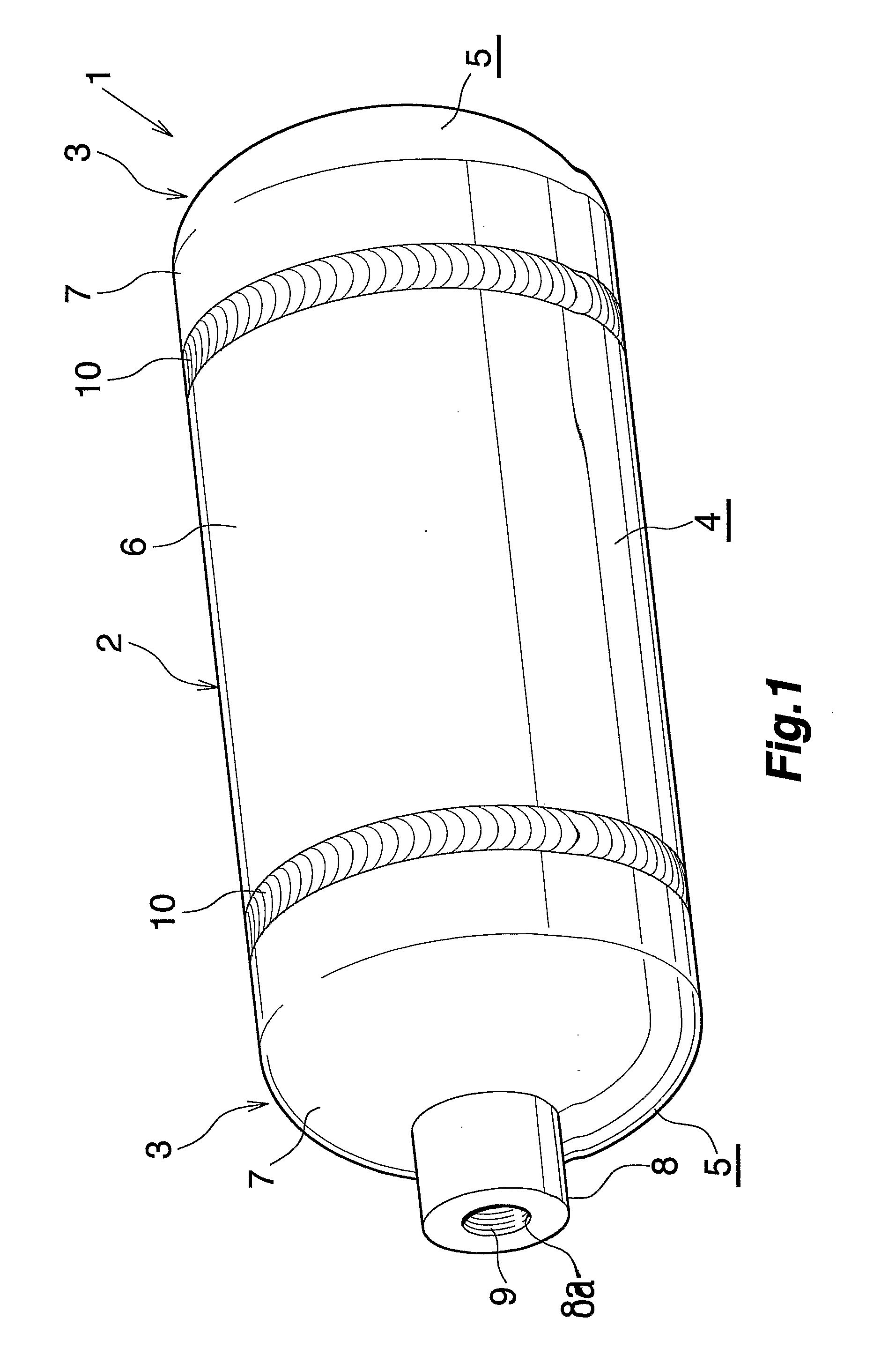
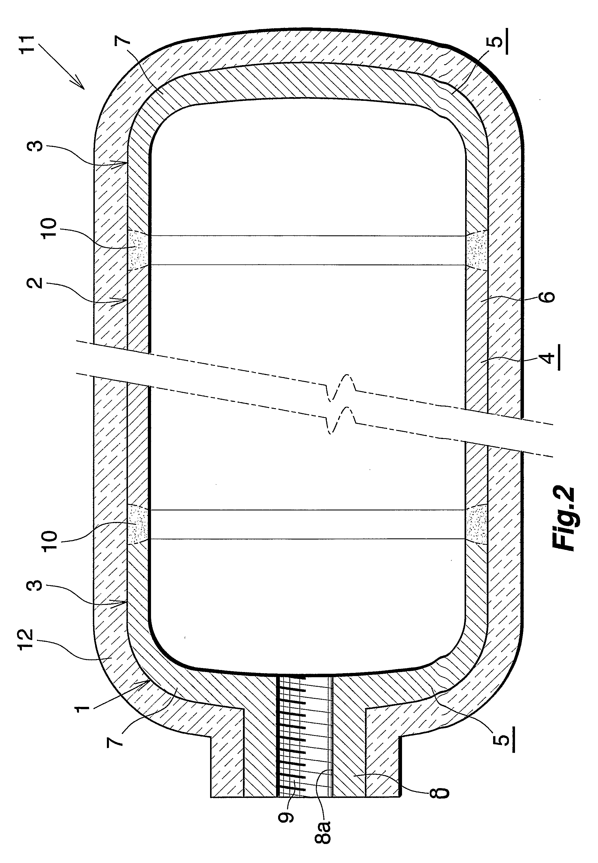
[0046]FIG. 1 shows the overall construction of a pressure vessel liner fabricated by a production process of the invention, and FIG. 2 is a high-pressure hydrogen gas vessel wherein the liner of FIG. 1 is used. FIGS. 3 and 4 show the process for fabricating the liner.

[0047]With reference to FIG. 1, the pressure vessel liner 1 comprises a hollow cylindrical trunk 2, and head plates 3 for closing openings at opposite ends thereof. More specifically, the liner 1 comprises a first liner component 4 made of an aluminum extrudate tube having an openings at each of opposite ends thereof and providing the trunk 2, and two second liner components 5 of aluminum joined to the respective opposite ends of the first component 4 and providing the head plates 3. The second liner components 5 are made by forging or cutting.

[0048]The first liner component 4 has a peripheral wall 6 having a circular cross secti...


PUM

PropertyMeasurementUnit
Thicknessaaaaaaaaaa
Angleaaaaaaaaaa
Timeaaaaaaaaaa

Abstract

A process prevents a reduction in the strength of the joint between the liner components, and assures high productivity without impairment. The peripheral walls (6, 7) of the liner component (4) and each of the second liner components (5) are brought into contact with each other, a probe (22) of friction agitation joining tool (20) is placed into the two liner components across the contact portions thereof, and the probe (22) in rotation is thereafter moved relative to the two liner components (4, 5). Assuming that the number of revolutions of the probe (22) is R rpm and that the speed of joining of the two liner components (4, 5) is V mm/min, R/V is in the range of 2≦R/V≦12.

Description

CROSS REFERENCE TO RELATED APPLICATION[0001]This application is an application filed under 35 U.S.C. §111(a) claiming the benefit pursuant to 35 U.S.C. §119(e)(1) of the filing date of Provisional Application No. 60 / 561,534 filed Apr. 13, 2004 pursuant to 35 U.S.C. §111(b).TECHNICAL FIELD[0002]The present invention relates to liners for use in pressure vessels for storing hydrogen gas or natural gas serving as a fuel for power generation, or for use in pressure vessels for storing oxygen gas, for example, in the automobile industry, housing industry, military industry, aerospace industry, medical industry, etc. and to a process for producing the liner.[0003]The term “aluminum” as used herein and in the appended claims includes aluminum alloys in addition to pure aluminum.BACKGROUND ART[0004]In order to control air pollution, efforts have been made in recent years for developing natural gas motor vehicles and fuel cell motor vehicles which produce clean emissions. These motor vehicle...

Claims


Application Information

Patent Timeline
IPC IPC(8): H01M8/18B23K20/12F17C1/02B23K33/00F02M21/02H01M8/00H01M8/04H01M8/06
CPCF17C2203/0665F17C2203/0668F17C2203/067F17C2209/222F17C2209/232F17C2221/011F17C2221/012F17C2221/033F17C2223/0123F17C2223/035F17C2223/036F17C2260/036F17C2265/07F17C2270/0168F17C2270/0178F17C2270/0184F17C2270/0194F17C2270/02F17C2270/05F17C2270/0763H01M8/04216Y02E60/321B23K20/123B23K33/006B23K2201/12B23K2203/10F17C1/06F17C1/16F17C2201/0109F17C2201/0166F17C2201/056F17C2203/0604F17C2203/0619F17C2203/0646F17C2203/0648B23K2101/12B23K2103/10Y02E60/32Y02E60/50
Inventor KANNO, YASUHARUOSAME, YASUHIRO
Owner SHOWA DENKO KK
Why Eureka
Try Eureka