Impregnated material with variable erosion properties for rock drilling and the method to manufacture

a technology of erosion properties and impregnated materials, which is applied in the direction of grinding devices, manufacturing tools, transportation and packaging, etc., can solve the problems of reducing the effect of hardness, affecting the quality of drilling, and contributing to the wear of supporting materials,

Active Publication Date: 2008-11-20
SMITH INT INC
View PDF23 Cites 89 Cited by
  • Summary
  • Abstract
  • Description
  • Claims
  • Application Information

AI Technical Summary

Problems solved by technology

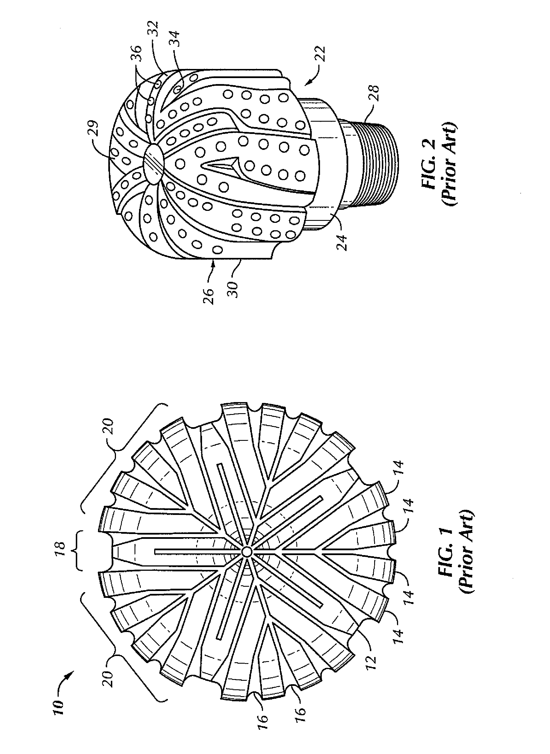
While bits having abrasive polycrystalline diamond cutting elements are known to be effective in some formations, they have been found to be less effective for hard, very abrasive formations such as sandstone.
The slurry must travel across the top of the rib before reentering the fluid paths, which contributes to wear of the supporting material.
For example, diamonds imbedded according to methods disclosed in the '202 patent have a total thermal exposure of less than 40 minutes, and more typically less than 20 minutes (and more generally about 5 minutes), above 1500° F. This limited thermal exposure is due to the shortened hot pressing period and the use of the brazing process.
The diamond clusters lack sufficient matrix material around them for good diamond retention.
The areas void or low in diamond concentration have poor wear properties.
Accordingly, the bit or insert may fail prematurely, due to uneven wear.

Method used


Image

  • Impregnated material with variable erosion properties for rock drilling and the method to manufacture
  • Impregnated material with variable erosion properties for rock drilling and the method to manufacture
  • Impregnated material with variable erosion properties for rock drilling and the method to manufacture

Examples


example 1

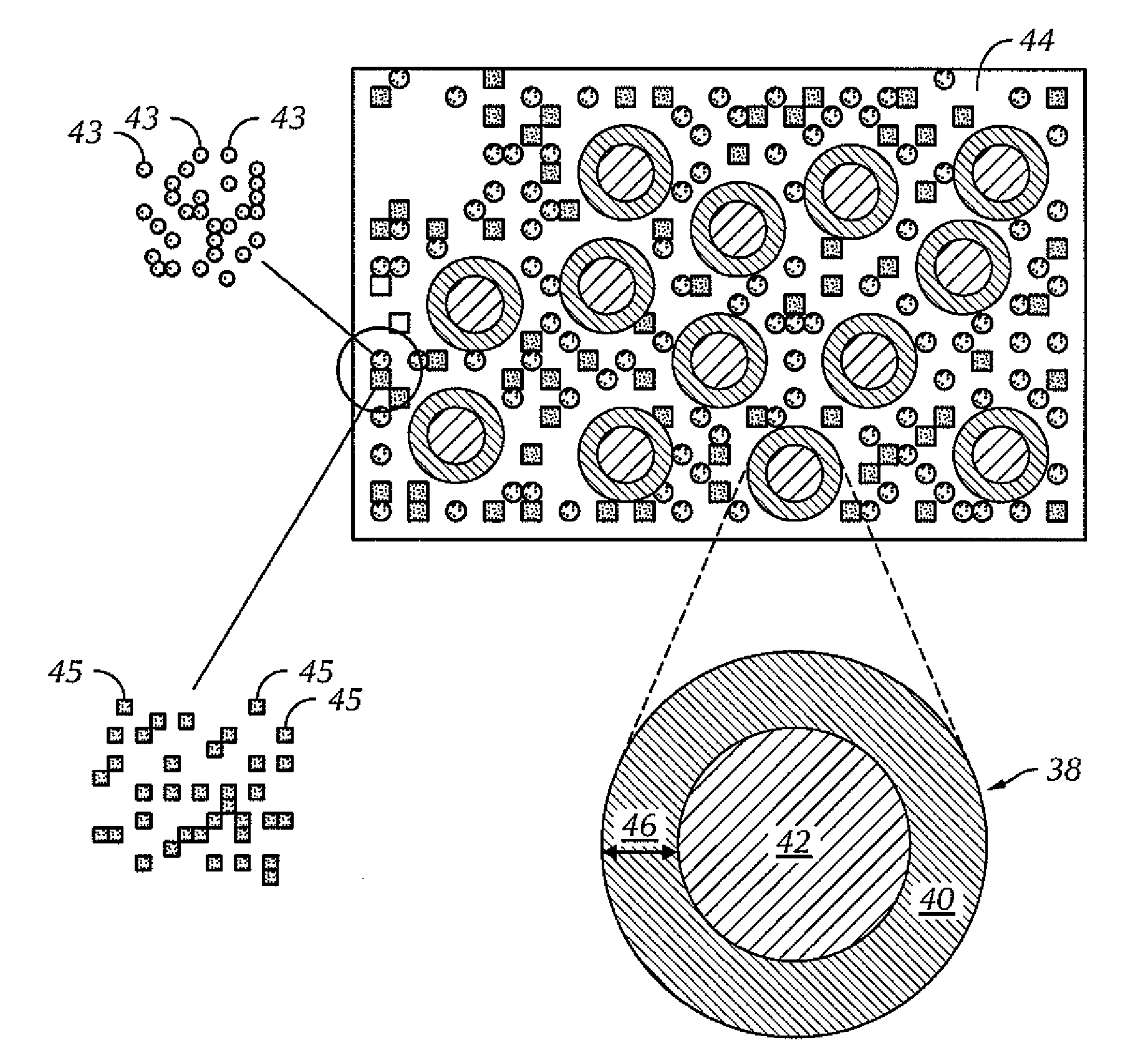
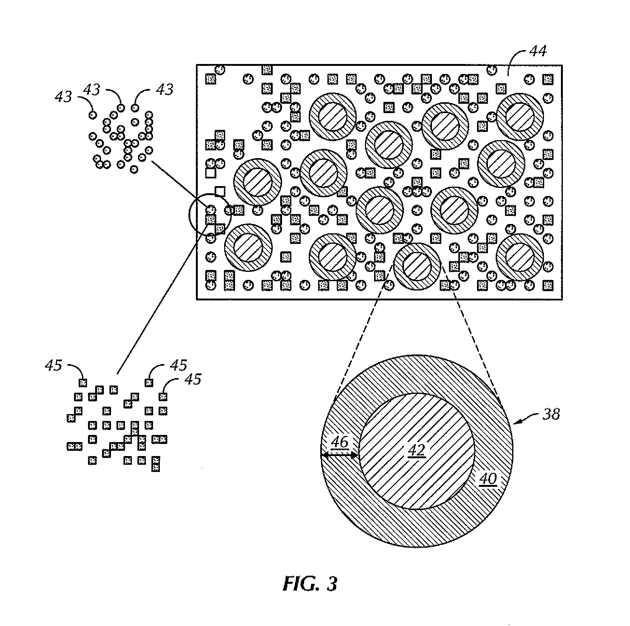
[0086]A sample impregnated cutting structure formed in accordance with embodiments of the present disclosure is compared to a comparative sample cutting structure formed by a conventional process. The exemplary impregnated cutting structure is made using encapsulated diamond particles ranging from 25 to 35 mesh. The shell encapsulating the abrasive grit includes 70% WC (0.8 to 3.0 micron particle size with an average of 2 microns), 20% Co, and 10% Cu. The encapsulated particles are placed into the mold, and tungsten shoulder powder (96% W-4% Ni) is then placed on top of the encapsulated particles. Binder cubes of a copper alloy (Cu-23Mn-11Ni-6Sn-4Zn) are further placed on top of the encapsulated particles. Infiltration of the matrix is carried out at 1030° C. Referring to FIG. 8, a scanning electron microscopy (SEM) image of a polished surface of the exemplary impregnated cutting surface is shown. FIG. 8 shows the abrasive grit 82 surrounded by a shell 80 of WC. The spaces between t...

example 2

[0090]A second sample impregnated cutting structure formed in accordance with embodiments of the present disclosure is compared to the comparative sample cutting structure described above. The exemplary impregnated cutting structure is made using encapsulated diamond particles ranging from 25 to 35 mesh. The shell encapsulating the abrasive grit includes 70% WC (0.8 to 3.0 micron particle size with an average of 2 microns), 20% Co, and 10% Cu. The encapsulated particles are placed into the mold (rib area), and a tungsten carbide matrix mixture that includes 61% agglomerated WC (MAS 3000-5000), 35% cast WC, 2% Ni, and 2% Fe is then placed on top of the encapsulated particles. Binder cubes of a copper alloy (Cu-23Mn-11Ni-6Sn-4Zn) are farther placed on top of the encapsulated particles. Infiltration of the matrix is carried out at 1030° C. Referring to FIG. 10, a scanning electron microscopy (SEM) image of a polished surface of the exemplary impregnated cutting surface is shown. FIG. 1...


PUM

PropertyMeasurementUnit
particle sizeaaaaaaaaaa
diameteraaaaaaaaaa
temperatureaaaaaaaaaa

Abstract

A cutting structure that includes a plurality of encapsulated particles dispersed in a first matrix material, the encapsulated particles comprising: an abrasive grit encapsulated within a shell, wherein the shell comprises a second matrix material different from the first matrix material is disclosed.

Description

CROSS-REFERENCE OF RELATED APPLICATIONS[0001]This application, pursuant to 35 U.S.C. § 119, claims the benefit of U.S. Patent Application No. 60 / 938,827, filed on May 18, 2007, which is herein incorporated by reference in its entirety.BACKGROUND OF INVENTION[0002]1. Field of the Invention[0003]Embodiments disclosed herein relate generally to drill bits, and more particularly to drill bits having impregnated cutting surfaces and the methods for the manufacture of such drill bits.[0004]2. Background Art[0005]An earth-boring drill bit is typically mounted on the lower end of a drill string and is rotated by rotating the drill string at the surface or by actuation of downhole motors or turbines, or by both methods. When weight is applied to the drill string, the rotating drill bit engages the earth formation and proceeds to form a borehole along a predetermined path toward a target zone.[0006]Different types of bits work more efficiently against different formation hardnesses. For examp...

Claims


Application Information

Patent Timeline
Patent Type & Authority Applications(United States)
IPC IPC(8): B24B1/00E21B10/36B22F1/18
CPCB22F2005/001B24D18/0027C22C1/101C22C1/1036C22C26/00Y10T428/2991C23C30/005E21B10/46B22F1/025E21B10/567C23C24/08B22F1/18
Inventor LOCKWOOD, GREGORY T.
Owner SMITH INT INC
Why Eureka
Try Eureka