Wheel Support Bearing Assembly with Built-In Load Sensor
- Summary
- Abstract
- Description
- Claims
- Application Information
AI Technical Summary
Benefits of technology
Problems solved by technology
Method used
Image
Examples
first embodiment
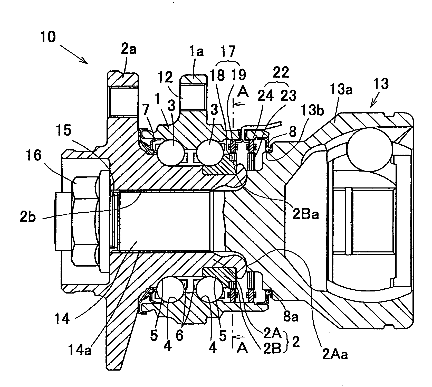
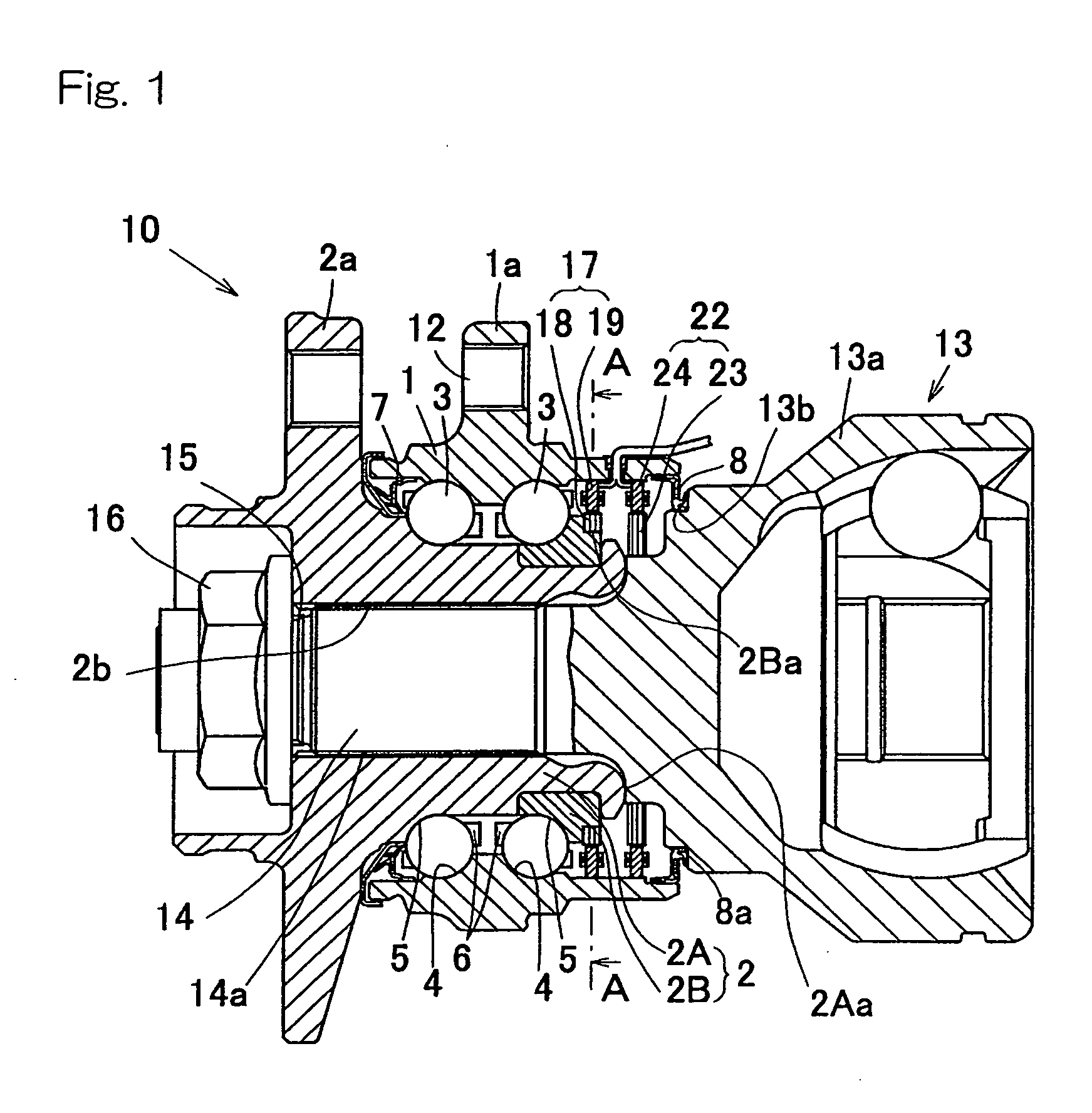
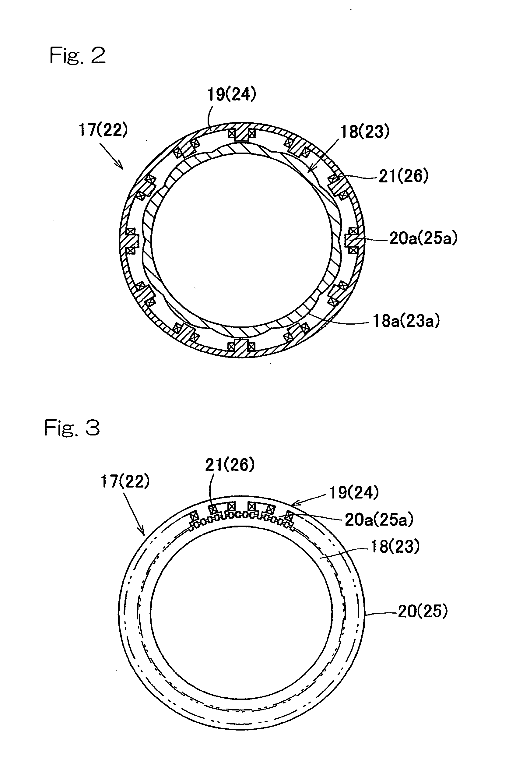
[0052]The first preferred embodiment of the present invention will be described with particular reference to FIGS. 1 to 4. A wheel support bearing assembly with a built-in load sensor is applied to a third-generation wheel support bearing assembly of an inner race rotating type that is used to support a drive wheel. It is to be noted that the terms “inboard” and “outboard” represent the sides facing the inside and the outside, respectively.
[0053]Referring to FIG. 1, the wheel support bearing assembly 10 includes an outer member 1 having an inner peripheral surface formed with double rows of raceway surfaces 4, an inner member 2 having an outer peripheral surface formed with double rows of raceway surfaces 5 confronting those raceway surfaces 4, and double rows of rolling elements 3 interposed between those double rows of the raceway surfaces 4 and 5. This wheel support bearing assembly 10 is a double row angular contact ball bearing. Each of the raceway surfaces 4 and 5 is of an ar...
second embodiment
[0066]A portion of the outer peripheral surface of the outer race 13a shown in FIG. 5A is provided with a to-be-detected part 40 of the second rotational angle detecting sensor 39 adjacent the inboard end face (the staked portion 2Aa in this second embodiment) of the hub axle 2A which contacts the outer peripheral surface of the outer race 13a. A detecting part 41 of the second rotational angle detecting sensor 39 is provided at a portion of the inner peripheral surface of the outer member 1 radially opposed to the to-be-detected part 40. The to-be-detected part 40 and the detecting part 41 altogether form the second rotational angle detecting sensor 39. Even this second rotational angle detecting sensor 39 is of the same construction as the first rotational angle detecting sensor 35. Specifically, as shown in FIG. 6 by the reference numerals depicted along with those of the first rotational angle detecting sensor 35, the to-be-detected part 40 is a magnetic encoder including an ann...
third embodiment
[0081]FIGS. 14 and 15 illustrate a fifth preferred embodiment of the present invention. This wheel support bearing assembly 10 with the built-in load sensor is such that in place of the rings 52 and 52 forming the pulsar ring in the third embodiment shown in and described with reference to FIGS. 9 to 11, a plurality of indentations 68 and a plurality of indentations 69 are provided on the respective outer peripheral surfaces of the outer race 13a and the inner race 2B adjacent a boundary between the outer race 13a and the inner race 2B so that the indentations 68 and the indentations 69 confront with each other in contact relation, as shown in a fragmentary enlarged view in FIG. 15. The indentations 68 and the indentations 69 are spaced equally in circumferential directions of the outer race 13a and the inner race 2B, respectively. The inner race 2B and the outer race 13a have the same outer diameter adjacent the boundary.
[0082]The indentations 68 and 69 are so arranged that they ar...
PUM
 Abstract
Description
Claims
Application Information
 - R&D
- Intellectual Property
- Life Sciences
- Materials
- Tech Scout
- Unparalleled Data Quality
- Higher Quality Content
- 60% Fewer Hallucinations
Browse by: Latest US Patents, China's latest patents, Technical Efficacy Thesaurus, Application Domain, Technology Topic, Popular Technical Reports.
© 2025 PatSnap. All rights reserved.Legal|Privacy policy|Modern Slavery Act Transparency Statement|Sitemap|About US| Contact US: help@patsnap.com


