
All-Fiber Architecture for an Embedded Flight Sensor for Aeropropulsion Applications

a technology of flight sensor and fiber optics, applied in the direction of optical radiation measurement, instruments, spectrometry/spectrophotometry/monochromators, etc., can solve the problems of inconvenient use of conventional sensor and feedback technology for monitoring the flight parameters of modern aircraft designs, inconsistent data, and inconvenient use of conventional sensor and feedback technology

Inactive Publication Date: 2008-11-20
ZOLO TECHNOLOGIES INC
View PDF18 Cites 35 Cited by
  • Summary
  • Abstract
  • Description
  • Claims
  • Application Information

AI Technical Summary

Benefits of technology

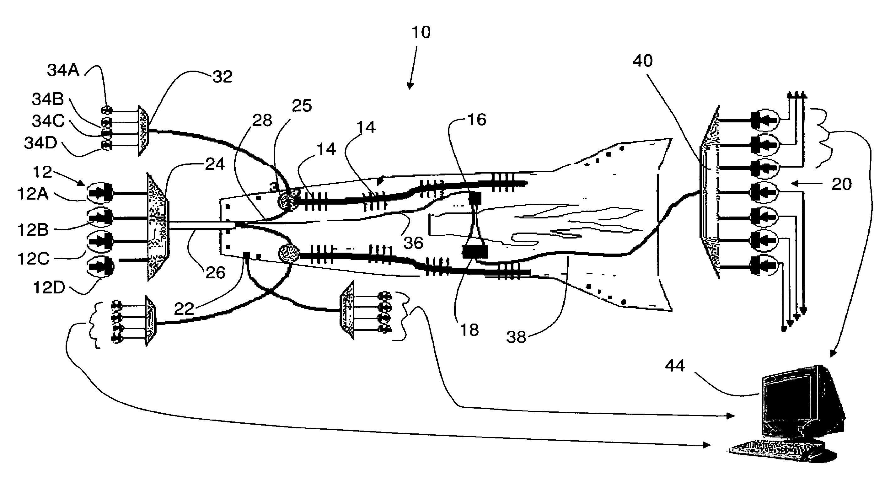
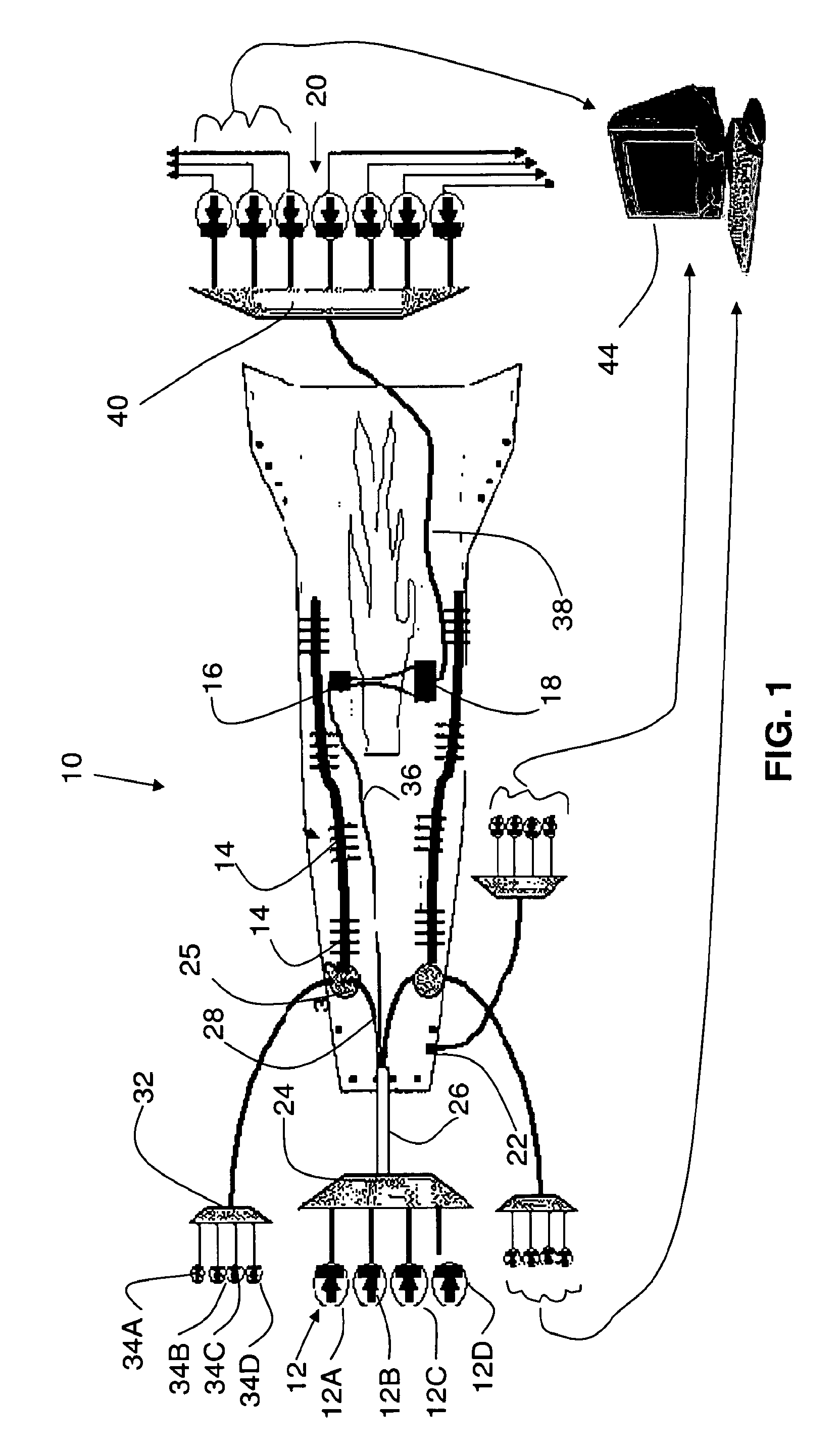
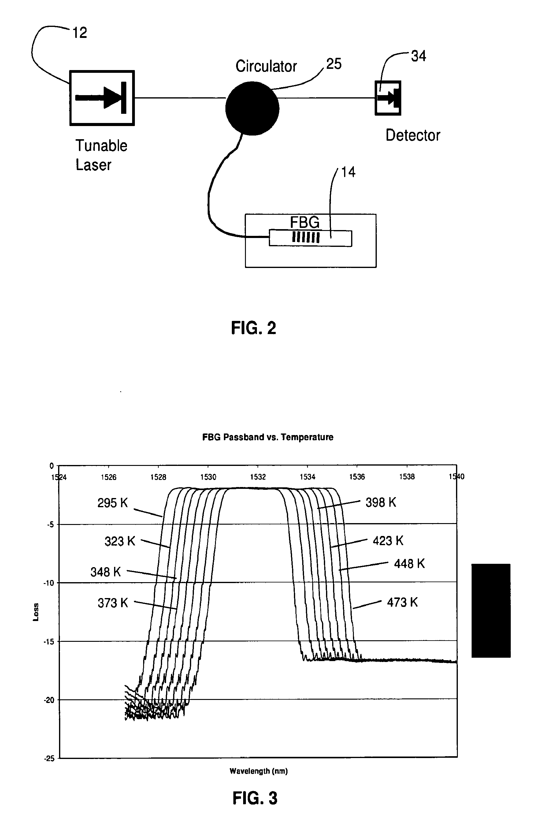
[0004]One aspect of the present invention is an embedded flight sensor system having a laser and one or more flight sensors in optical communication with the laser plus a data processing device in optical communication with the flight sensors. The flight sensors may be laser based optical components such as a fiber Bragg grating in combination with an optical detector, a spectroscopy grating and detector or an optical detector associated with catch optics. The parameters sensed by the flight sensors may be used to determine any flight parameter. Representative flight parameters include but are not limited to an airframe or external surface temperature, airstream velocity, combustion zone temperature, engine inlet temperature, a gas concentration or a shock front position.

Problems solved by technology

Conventional sensor and feedback technologies are in many instances poorly suited for the monitoring of the flight parameters of modern aircraft designs.
A series of independently located and independently operated sensing subsystems can also lead to inconsistent data, since the various sensing subsystems may not be in communication with each other.
Discrete sensing systems can also add excess weight and operational complexity.

Method used


Image

  • All-Fiber Architecture for an Embedded Flight Sensor for Aeropropulsion Applications
  • All-Fiber Architecture for an Embedded Flight Sensor for Aeropropulsion Applications
  • All-Fiber Architecture for an Embedded Flight Sensor for Aeropropulsion Applications

Examples


Embodiment Construction

[0019]Optical Fiber Coupled Architecture

[0020]The present invention includes an optical fiber coupled system of laser-based sensors for measuring various parameters associated with powered flight. Also disclosed is an architecture for coupling the sensors together into a fully integrated package suitable for embedded flight applications. The ultimate goal of the system and architecture is to acquire data necessary to optimize engine or other flight parameters through feedback control. The system, architecture and sensor technology described herein are appropriate for conventional gas turbine propulsion systems as well as developing SCRAMJET, rocket engine, and pulsed detonation engine technologies. The system may include, but is not limited to, sensors to measure engine inlet flow speed, engine inlet oxygen concentration and temperature. In addition, the temperature and water concentration in the combustion zone plus the position of shock waves in the engine inlet for supersonic and...


PUM


Abstract

An embedded flight sensor system having a laser and one or more flight sensors in optical communication with the laser plus a data processing device in optical communication with the flight sensors. The flight sensors may be laser based optical components such as a fiber Bragg grating in combination with an optical detector, a spectroscopy grating and detector or an optical detector associated with catch optics. The parameters sensed by the flight sensors may be used to determine any flight parameter. Representative flight parameters include but are not limited to an airframe or external surface temperature, airstream velocity, combustion zone temperature, engine inlet temperature, a gas concentration or a shock front position.

Description

TECHNICAL FIELD[0001]The present invention relates an all fiber sensor architecture and method for use in embedded flight applications.BACKGROUND OF THE INVENTION[0002]Modern aircraft are being developed which feature increasingly sophisticated propulsion systems. In particular, conventional gas turbine engines, SCRAMJET, rocket engine and pulse detonation engine technologies are being designed and built to power future generations of aircraft. In conjunction with the development of advanced engine technologies, airframe and aircraft skin technologies have advanced to develop suitable structures and flight surfaces to support the next generation of aircraft.[0003]In many instances, the technologically advanced modern engine designs plus advanced flight surface structures require onboard feedback and control systems to assure that the various components are performing properly within specific design parameters. For example, the exterior flight surface temperature of a hypersonic airc...

Claims


Application Information

Patent Timeline
Patent Type & Authority Applications(United States)
IPC IPC(8): G02B6/26
CPCG01J3/1895G01J5/0014G01J5/0018G01J5/08G01J5/0803G01J5/0821G01J5/0893G01J5/0896G01J5/60G01K11/3206G01N21/39G01P5/26
Inventor SAPPEY, ANDREW D.MASTERSON, BERNARD PATRICK
Owner ZOLO TECHNOLOGIES INC
Learn More