Device and Methods for Suturing Tissue

a tissue and suture technology, applied in the field of tissue suture devices and methods, can solve the problems of increased incidence of complications, ischemia and/or thrombosis, and uncomfortable procedures for patients

Inactive Publication Date: 2008-11-20
ABBOTT LAB INC
View PDF20 Cites 116 Cited by
  • Summary
  • Abstract
  • Description
  • Claims
  • Application Information

AI Technical Summary

Benefits of technology

[0029]A method for suturing a tissue layer having two sides is also provided by the present invention. The steps of the method include: releasably retaining at least a...

Problems solved by technology

It is time-consuming, frequently requiring one-half hour or more of compression before hemostasis is assured.
This procedure is uncomfortable for the patient and frequently requires administering analgesics to be tolerable.
Moreover, the application of excessive pressure can at times totally occlude the underlying blood vessel, resulting in ischemia and/or thrombosis.
The incidence of these complications increases when the sheath size is increased and when the patient is anti-coagulated.
It is clear that the standard technique for arterial closure can be risky, and is expensive and onerous to the patient.
While the risk of such conditions can be reduced by using highly trained individuals, such use is both expensive and inefficient.
While potentially effective, this approach suffers from a number of problems.
It can be difficult to properly locate the interface of the overlying tissue and the adventitial surface of the blood vessel, and locating the fastener too far from that surface can result in failure to provide hemostasis and subsequent hematoma and/or pseudo aneurism formation.
Conversely, if the fastener intrudes into the arterial lumen, intravascular clots and/or collagen pieces with thrombus attached can form and embolize downstream causing vascular occlusion.
Also, thrombus formation on the surface of a fastener protruding into the lumen can cause a stenosis which can obstruct normal blood flow.
Other possible complications include infection as well as adverse reactions to the collagen implant.
In fact, heart disease patients oft...

Method used


Image

  • Device and Methods for Suturing Tissue
  • Device and Methods for Suturing Tissue
  • Device and Methods for Suturing Tissue

Examples


Embodiment Construction

[0083]As used herein, the term “distal” is generally defined as in the direction of the patient, or away from a user of a device, or in a downstream direction relative to a forward flow of blood. In the context of a medical device intervention with or through a vessel wall, “distal” herein refers to the interior or the lumen side of the vessel wall.

[0084]Conversely, “proximal” generally means away from the patient, or toward the user, or in an upstream direction relative to a forward flow of blood. In the context of a medical device intervention with or through a vessel wall, “proximal” herein refers to the exterior or outer side of the vessel wall.

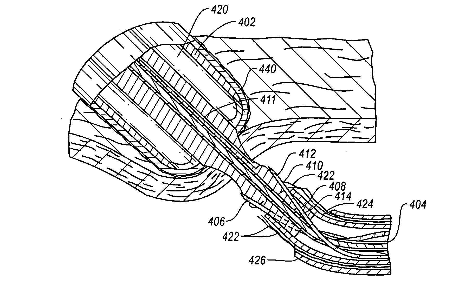
[0085]Additionally, “oblong” is herein intended to mean oval, elliptical, or otherwise having a generally rounded shape that is not perfectly circular. In particular, the term describes the shape of a tubular graft end cut at an acute angle relative to the plane perpendicular to the tissue walls defining the graft.

[0086]The term “hemostas...


PUM


Abstract

Systems for suturing a tissue layer having two sides with a suture be releasably retaining at least a portion of the suture in a stationary position on one side of the tissue layer. The portion of the suture is retrieved through the tissue layer from the opposite side whereby the suture is drawn from one side to the opposite side. Systems for suturing the wall of a tubular graft having two sides is also provided using a suture by releasably retaining at least a portion of the suture on one side of the wall. the portion of the length of suture is retrieved through the wall of the graft to the opposite side of the wall.

Description

CROSS-REFERENCE TO RELATED APPLICATIONS[0001]This application is a continuation of U.S. patent application Ser. No. 10 / 737,668, filed Dec. 16, 2003, which is a continuation of U.S. patent application Ser. No. 10 / 033,689, filed Dec. 28, 2001, which is a continuation of U.S. patent application Ser. No. 08 / 883,246, filed Jun. 26, 1997, now U.S. Pat. No. 6,355,050, which is a continuation-in-part of U.S. patent application Ser. No. 08 / 824,031, filed Mar. 26, 1997, now U.S. Pat. No. 6,036,699, which is a continuation-in-part of U.S. patent application Ser. No. 08 / 259,410, filed Jun. 14, 1994, now U.S. Pat. No. 5,779,719, which is a divisional and a continuation-in-part of U.S. application Ser. No. 07 / 989,611, filed Dec. 10, 1992, now U.S. Pat. No. 5,417,699. The disclosures of these prior applications are hereby incorporated by reference in their entirety.FIELD OF THE INVENTION[0002]The present invention relates generally to devices and methods for the suturing of tissue in various appli...

Claims


Application Information

Patent Timeline
IPC IPC(8): A61B17/062A61B17/00A61B17/04A61B17/06A61B17/12A61F2/00
CPCA61B17/0057A61B17/0401A61B17/0469A61B17/0482A61B17/06066A61B17/0625A61B2017/00004A61B2017/00637A61B2017/00641A61B2017/00663A61B2017/00867A61B2017/0458A61B2017/0464A61B2017/047A61B2017/0472A61B2017/0474A61B2017/06057A61F2002/30093A61F2210/0019Y10S604/90A61F2002/30092
Inventor ANDREAS, BERNARD H.BARRETT, MICHAELFOLEY, MARK J.GORE, BRIANISBELL, LEWISSONGER, RONALDVETTER, JAMES W.
Owner ABBOTT LAB INC
Why Eureka
Try Eureka