Method of Attaching Radiopaque Markers to Intraluminal Medical Devices, and Devices Formed Using the Same

Active Publication Date: 2008-11-20
BOSTON SCI SCIMED INC
View PDF40 Cites 27 Cited by
  • Summary
  • Abstract
  • Description
  • Claims
  • Application Information

AI Technical Summary

Benefits of technology

[0026]The method according to the present invention decreases the possibility of stress and

Problems solved by technology

These shape memory alloys, however, are not highly radiopaque.
Some att

Method used


Image

  • Method of Attaching Radiopaque Markers to Intraluminal Medical Devices, and Devices Formed Using the Same
  • Method of Attaching Radiopaque Markers to Intraluminal Medical Devices, and Devices Formed Using the Same
  • Method of Attaching Radiopaque Markers to Intraluminal Medical Devices, and Devices Formed Using the Same

Examples


examples

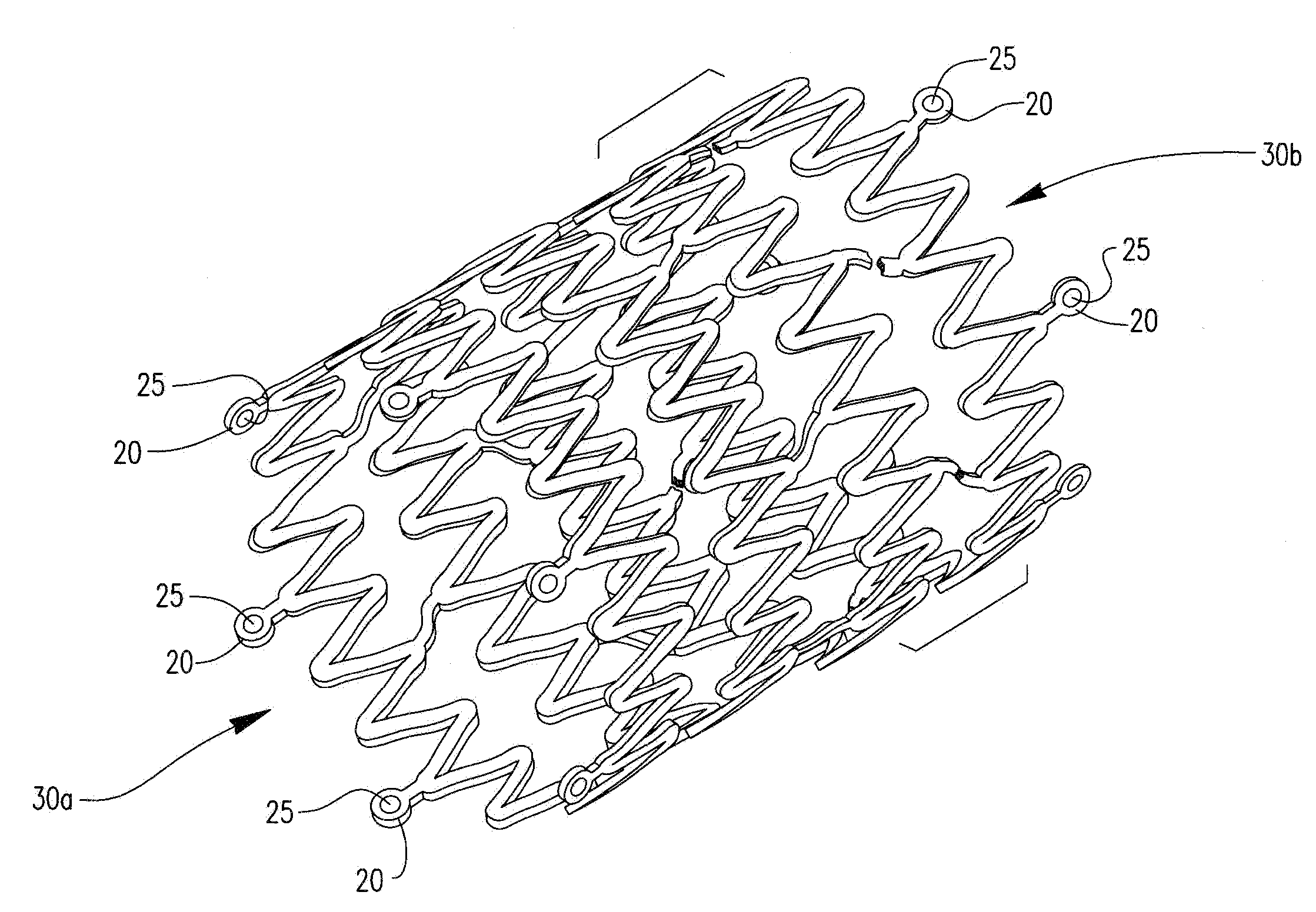
[0059]In at least one embodiment a sample frame work was supplied with a radiopaque marker element according to the method described as illustrated by the following example.

example

[0060]Testing conditions:

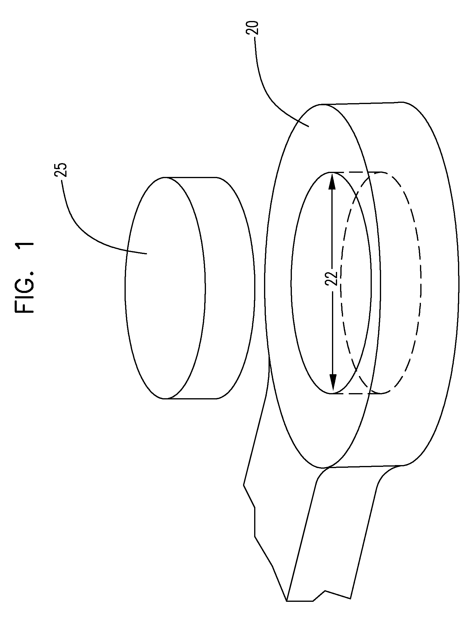
[0061]Nominal hole=0.0200 inches

[0062]Least material condition (LMC)=+0.0004 inches

[0063]Maximum material condition (MMC)=−0.0004″

[0064]Marker element=0.0187″×0.0070″ (Tantalum)

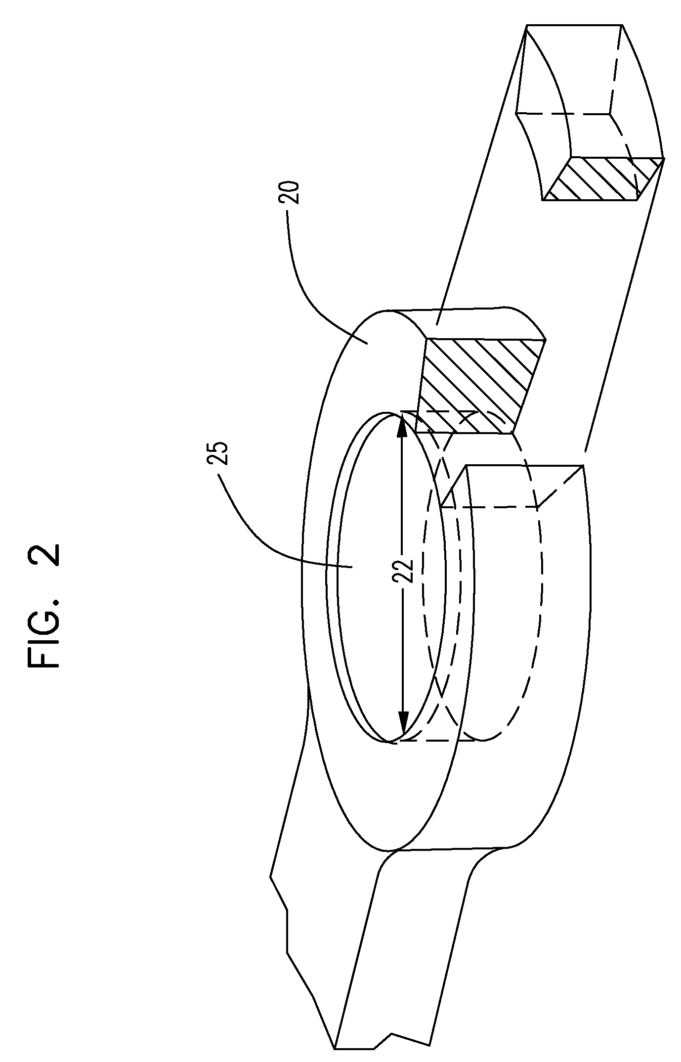
[0065]Nitinol nickel-titanium alloy impression diameter=0.024″

[0066]Center swage diameter=0.017″

[0067]First force during swage (Nitinol impression force)=95 pounds

[0068]Center swage force=53 pounds with a 12 pound paddle hold down force

[0069]Thermal conditioning was conducted at 250° C. for 300 seconds in drywell.

[0070]A range of various temperatures and times were evaluated in characterizing the shape recovery process. Confirmation of the shape recovery effects were demonstrated through dimensional change of paddle before and after thermal conditioning as well as performance improvements in the force required to dislodge the marker from paddle and fracture resistance through high frequency low alternating strains (ultrasonic testing).

[0071]Temperatures sufficient to induce a martensi...


PUM

PropertyMeasurementUnit
Temperatureaaaaaaaaaa

Abstract

A method of attaching radiopaque markers to an intraluminal medical device frame formed from a shape memory metal or alloy thereof, the process conducted during the shape recovery process of said shape memory metal or alloy thereof.

Description

FIELD OF THE INVENTION[0001]The present invention relates to the field of implantable medical devices such as stents, which incorporate markers for increasing visibility during a procedure.BACKGROUND OF THE INVENTION[0002]Intraluminal medical devices, such as stents, can be implanted into a body lumen during a non-invasive clinical procedure, to reinforce, support, repair or otherwise enhance the performance of the lumen. Percutaneous transluminal angioplasty (PTA), for example, is a procedure used to increase the blood flow through a coronary artery, for example, at a location where the artery is damaged or is susceptible to collapse. The stent, once in place, reinforces that portion of the artery allowing normal blood flow to occur through the artery.[0003]One type of stent which is often used for implantation in arteries and other body lumens is a cylindrical stent which can be radially expanded from a first smaller diameter to a second larger diameter. Such radially expandable s...

Claims


Application Information

Patent Timeline
IPC IPC(8): A61F2/06
CPCA61F2/91A61F2/915A61F2002/91558A61F2250/0098C22F1/006Y10T29/49915A61F2230/0054Y10T29/49911Y10T29/49867Y10T29/49934F05C2251/08
Inventor HEMERICK, JAMES F.CHAU, THYNAANDERL, STEVEDAVIS, MICHAEL L.CHOUINARD, PAUL F.FINANDER, BRIAN
Owner BOSTON SCI SCIMED INC
Why Eureka
Try Eureka