
Method and Apparatus of Detecting an Object

a technology of object detection and object detection, applied in the direction of instruments, specific gravity measurement, analysis of fluids using sonic/ultrasonic/infrasonic waves, etc., can solve the problem of inability to detect potential harmful materials in closed containers, lack of sensitivity or specificity, and inability to use x-ray radiation for safety or health reasons, etc. problems, to achieve the effect of simple setup and operation, and decrease of variance and operating costs

Inactive Publication Date: 2008-11-27
BRANDT INNOVATIVE TECH
View PDF26 Cites 13 Cited by
  • Summary
  • Abstract
  • Description
  • Claims
  • Application Information

AI Technical Summary

Benefits of technology

[0024]Another aspect of the invention is to provide an apparatus that is ruggedized and reliable, thereby decreasing down time and operating costs.
[0025]Still another aspect of the invention is to provide an apparatus that has one or more of the characteristics discussed above but which is relatively simple to manufacture, assemble, and use using a minimum of equipment, time and resources. In one such a manufacturing process, subsystems would be purchased from other manufacturers and final assembly and integration of these subsystems would be done at a central location.
[0033]Another aspect of the invention is to provide a method that can be used to satisfy the above aspects of the invention. Still another aspect of the invention is to provide a method that is predictable and reproducible, thereby decreasing variance and operating costs.
[0034]Another aspect of the invention is to provide a method that has one or more of the characteristics discussed above but which is which is relatively simple to setup and operate using relatively low skilled workers.

Problems solved by technology

As is known to those skilled in the art, the detection of potential harmful materials in a closed container continues to be a problem.
This is particularly true where X-Ray radiation cannot be employed for safety or health reason, lack of sensitivity or specificity.
Other techniques such as contact-based ultrasound, optical spectroscopy, gas chromatography, mass spectroscopy, bio-assay etc. also lack the ability to perform stand-off, non-invasive, continuous, real-time, non-consumable inspection of closed containers that include plastic, glass, ferrous and non-ferrous metals.

Method used


Image

  • Method and Apparatus of Detecting an Object
  • Method and Apparatus of Detecting an Object
  • Method and Apparatus of Detecting an Object

Examples


Embodiment Construction

[0045]The present invention and the various features and advantageous details thereof are explained more fully with reference to the non-limiting embodiments described in detail in the following description.

1. System Overview

[0046]In one embodiment, the inventive system of the present invention includes an optical device that may be mounted on an optical “breadboard.” The breadboard may be mounted on a rail to enable the distance between a sensor of the system and a target container to be varied in a controllable way.

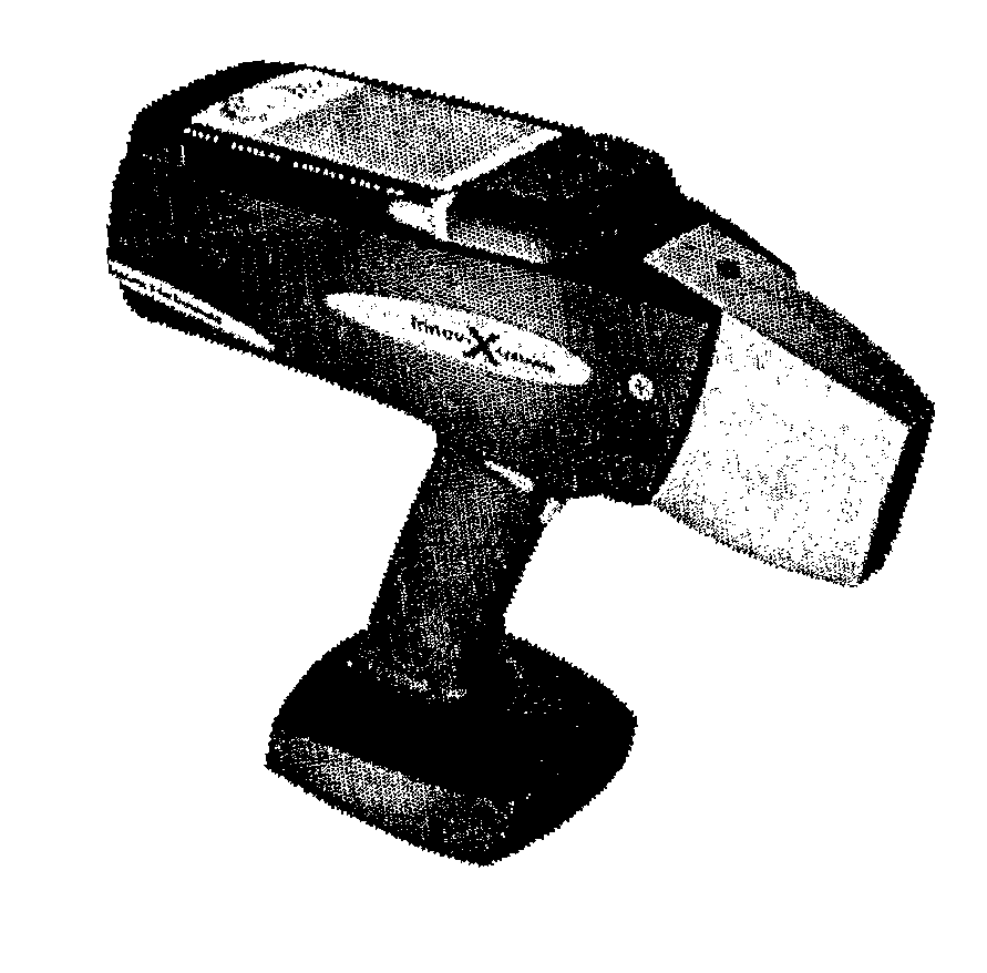
[0047]In another embodiment the inventive system of the present invention includes all optics, electronics, and software in a single hand-held unit, see e.g., FIG. 5.

[0048]The preferred optical device includes an excitation laser that will be a Q-switched Nd:Yag laser pumped with a laser diode. The entire laser will be preferably housed in a TO-3 case; have a Wavelength: 1.550 μm, Pulse Energy: 100 μJ, Pulse Width: 2 ns, Peak Power: 50 Kw, Repetition Rate: SS to 10 Hz a...


PUM

PropertyMeasurementUnit
wavelength rangeaaaaaaaaaa
Wavelengthaaaaaaaaaa
wavelength rangeaaaaaaaaaa

Abstract

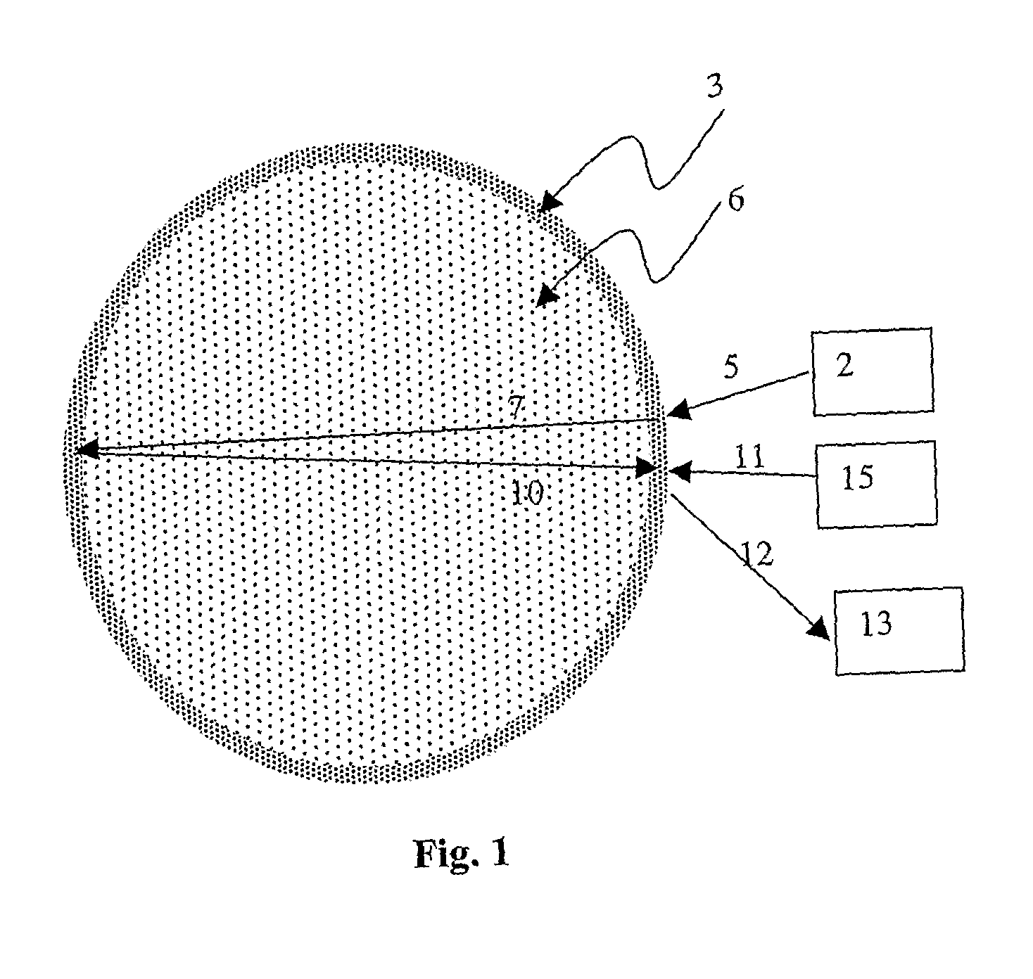
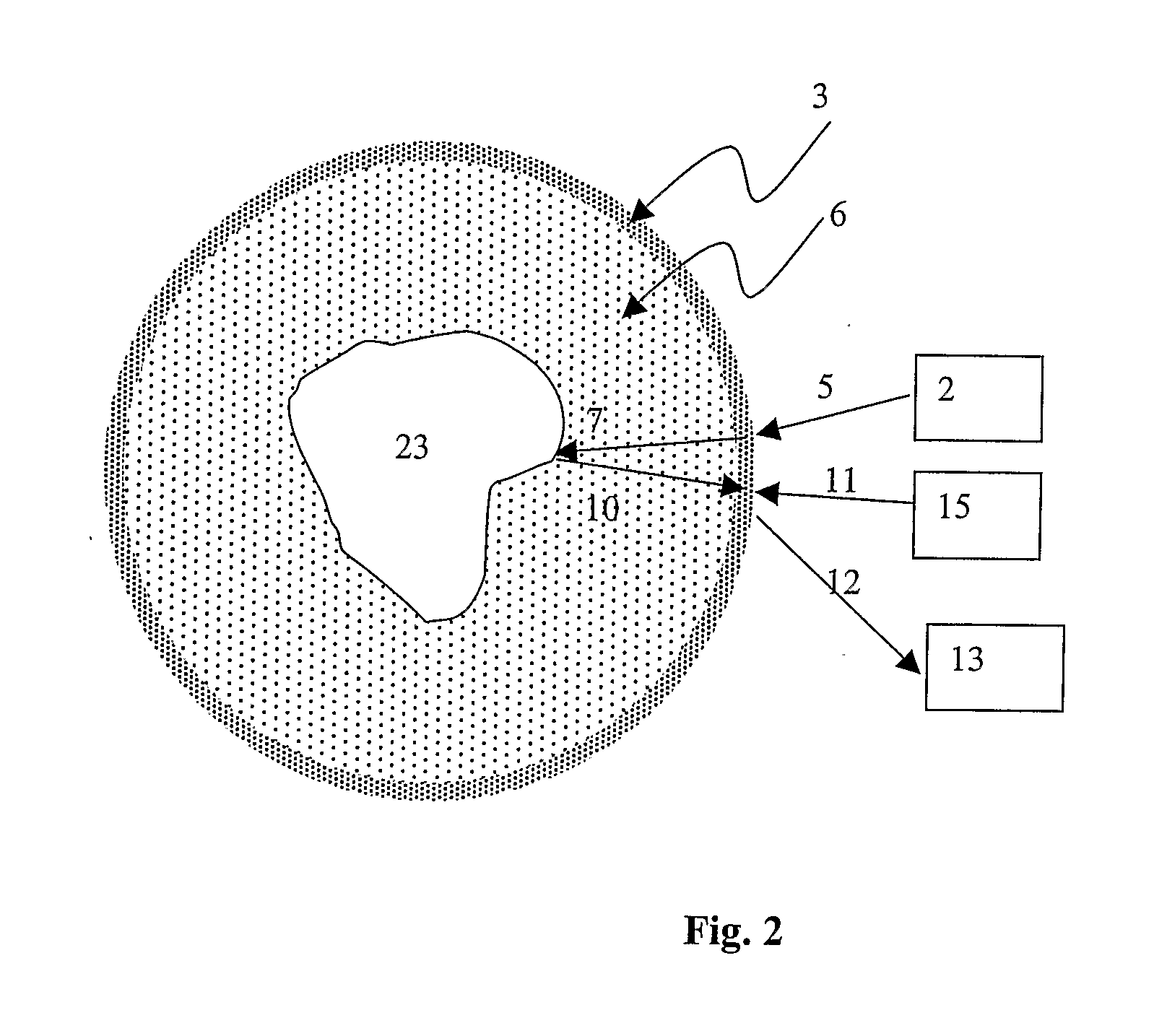
A system for stand-off, continuous, real-time, non-invasive, non-radiological, eye-safe, non-consumable characterization of an object is disclosed that comprises in combination a pulsed laser emitter for directing energy at the surface of an object, wherein the ultrasonic wave is generated within the object to be characterized, and a remote means of measuring the vibrational excitation in the object, whereby the object is remotely characterized.

Description

CROSS-REFERENCE TO RELATED APPLICATIONS[0001]This application claims priority from U.S. Provisional Patent Application Ser. No. 60 / 677,751, filed on May 4, 2005, the entity of which is expressly incorporated by reference herein in its entirety.FEDERALLY-SPONSORED RESEARCH AND DEVELOPMENT[0002]The U.S. Government has provided funding for the background research for this invention through an award by the Department of DefenseBACKGROUND OF THE INVENTION[0003]1. Field of the Invention[0004]The present invention relates in general to the field of safety, security and process control. More particularly, the present invention relates to a method and apparatus for detecting potential harmful objects in a closed container, measuring critical-to-quality parameters in a container's contents for process control and identifying defects in the container itself.[0005]2. Discussion of the Related Art[0006]As is known to those skilled in the art, the detection of potential harmful materials in a clo...

Claims


Application Information

Patent Timeline
Patent Type & Authority Applications(United States)
IPC IPC(8): G01N29/02G01N29/04
CPCG01H9/00G01N29/12G01N29/2418G01N2291/014G01N2291/2695G01H9/008
Inventor BRANDT, ROBERT KURTWILLIAMSEN, MARK STEPHEN
Owner BRANDT INNOVATIVE TECH
Learn More