
Electrode for a thermal battery and method of making the same

a technology of electric motor and thermal battery, which is applied in the direction of electromechanical devices, thermoelectric devices, deferred-action cells, etc., can solve the problems of large space occupied by large automated presses, blending equipment, and drying ovens, and the cumulative time involved in just the preparation of the final separator mix is quite larg

Inactive Publication Date: 2008-11-27
ELECTRO ENERGY
View PDF11 Cites 45 Cited by
  • Summary
  • Abstract
  • Description
  • Claims
  • Application Information

AI Technical Summary

Benefits of technology

"The patent describes a way to make a thermal electrode by creating a slurry made of components and water, and then spraying or sticking it onto a substrate. The density of the slurry can be adjusted by compressing the substrate. The size and shape of the electrode can be cut or punched from a sheet. Different binders can be used to change the thickness and viscosity of the electrode. The technical effect of this patent is a simplified and flexible method for making thermal electrodes."

Problems solved by technology

This can require a large amount of space for the large automated presses, blending equipment, and drying ovens and furnaces.
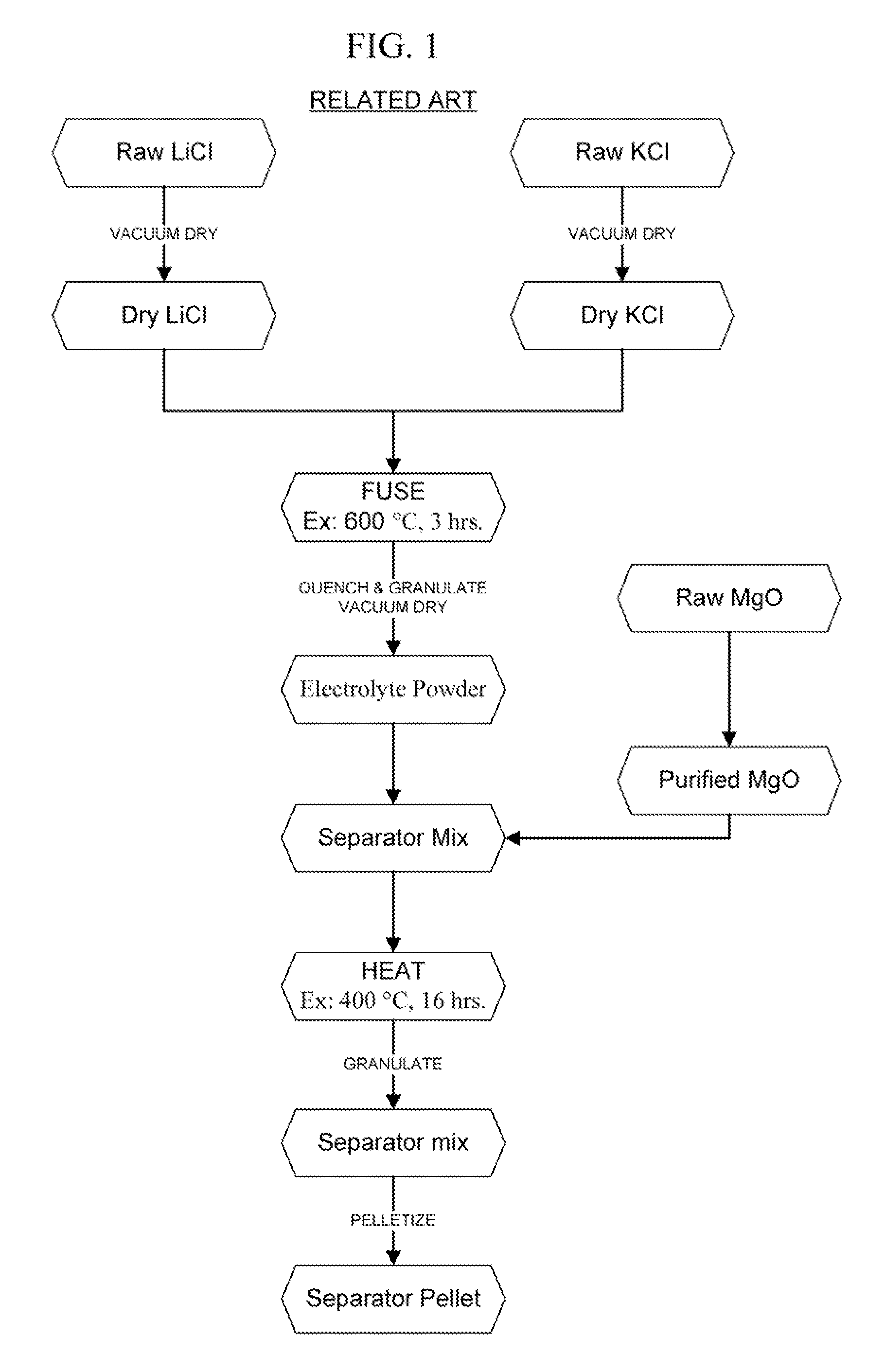
Thus, the cumulative time involved in just the preparation of the final separator mix is quite large.
One challenge when using pellet technology is the need for increasing press sizes as the diameter of the pellet is increased, since the pressure required for pressing increases as the square of the diameter.
An extensive die inventory can become quite expensive and can require a large amount of processing and / or storage space.
In addition, maintenance costs and efforts can increase with an increasing number of dies.
Another issue with the use of discrete pellets involves the large number of parts that are needed per cell.
This results from the need to make the pellets thicker strictly for mechanical reasons.
In addition, if the pellets are too thin, they are subject to chipping and breakage while handling during battery-stack assembly.
There is also the danger of soft, low-density spots when pressing thin separator pellets with diameters greater than 2″.
This can give rise to formation of a hole in the separator upon melting of the electrolyte, leading to breach of a cell.
Such a short will allow direct contact of the anode and cathode, resulting in very exothermic reactions taking place.
Such reactions can lead to a thermal-runaway condition in which the battery destroys itself.
Since FeS2 thermally decomposes above 550 ° C., using such material as a feedstock alone would not be practical.
However, the presence of elemental sulfur in the pyrite cathode of a thermal battery often gives rise to a voltage “spike” at the start of discharge, which is unacceptable, since such batteries typically have strict voltage regulation limits imposed on them.
However, plasma spraying is not an optimal electrode construction technique for several reasons.
For one, it requires the use of expensive equipment.
Typical plasma-spraying equipment is quite expensive and requires significant space and considerable skill in operation.
Some materials do not flow very well, resulting in a variable, nonuniform rate of deposition.
Another drawback of plasma spraying is that the composition of the deposit is not the same as that of the feedstock, with the electrolyte concentration in the deposit being much higher.
This lack of control of composition would not be acceptable for commercial production of thermal batteries.
Furthermore, the deposit density is low and can't be readily controlled.
Low separator densities can result in collapse of the electrode structure during discharge, reducing the interfacial contact between electrodes and causing an increase in impedance.
Plasma spraying is also intrinsically a batch process, which greatly reduces the throughput that is possible.
It is also difficult to maintain dimensional control of the electrode after the heat treatment, which can affect initiation of the resulting battery.

Method used


Image

  • Electrode for a thermal battery and method of making the same
  • Electrode for a thermal battery and method of making the same
  • Electrode for a thermal battery and method of making the same

Examples


Embodiment Construction

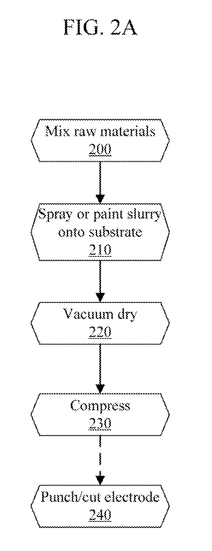
[0040]An aqueous slurry can be used to fabricate thermal electrodes (i.e., electrodes suited for use in a thermal battery) on a current collector substrate by painting (spraying) or pasting. As used herein, “pasting” includes the process of doctor-blading. As used herein, “spraying” refers to painting a layer using a spray gun or other controllable nozzle, but does not include processes such as plasma spraying. For electrodes about 0.005 inches thick or less, spraying may be preferred, whereas pasting may be preferred to achieve thicker electrodes. Generally, the fabrication of the slurry and subsequent electrode fabrication steps are the same for spraying and pasting. FIG. 2A shows an exemplary process for fabricating a thermal battery electrode by spraying or pasting. An aqueous slurry can be formed by mixing a thermal electrode material, a thermal electrolyte material, and water 200. As used herein, a “thermal” electrode, electrolyte, or other material or component is one that is...


PUM

PropertyMeasurementUnit
operating temperatureaaaaaaaaaa
current densitiesaaaaaaaaaa
weight percentaaaaaaaaaa

Abstract

An aqueous slurry can be used to paint thermal electrodes onto a current-collector substrate with a spray gun for thin electrodes or pasting with a thickened slurry. A feedstock aqueous slurry can include thermal electrode components, thermal electrolyte components, a binder or thickening agent, and water. This slurry can be sprayed or pasted onto a substrate and dried. To obtain different densities, the substrate can be compressed to a desired density. Thermal electrodes of a desired size and shape can be cut or punched from the sheet. Different binders and / or binder concentrations can be used to adjust the viscosity and / or thickness of the electrode.

Description

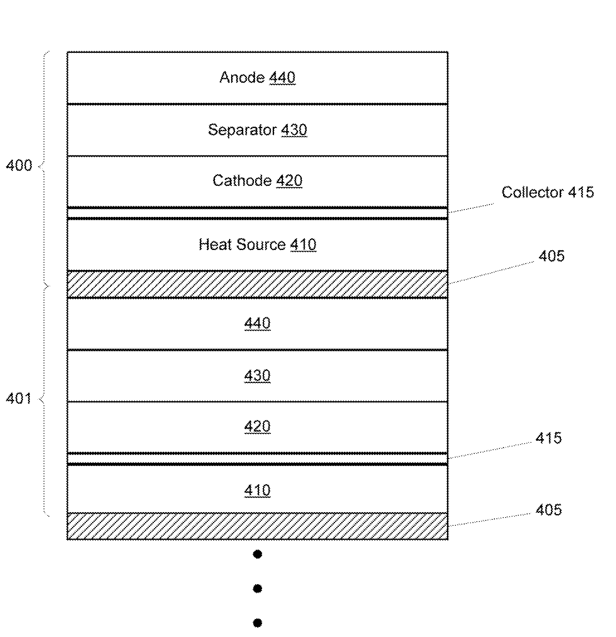
BACKGROUND[0001]Thermal batteries are used in a variety of applications. Typically, thermal batteries have a long shelf life and can be used under a wide temperature regime under severe environmental conditions, such as high shock, vibration, and spin.[0002]A typical thermal battery uses a molten-salt electrolyte as the ionically conductive medium. At room temperature, the salt is solid, but upon application of an electrical or mechanical signal, the battery is activated and the internal pyrotechnic brings the battery up to its operational temperature. A typical operating temperature for a thermal battery may be as high as 400-550° C. Molten salts can have an ionic conductivity several orders of magnitude higher than materials used in conventional batteries, such as Li-ion batteries, allowing for very high power levels to be achieved.[0003]A standard thermal battery consists of a stack of cells, each containing an anode, a separator, a cathode, and a pyrotechnic source. Typically, e...

Claims


Application Information

Patent Timeline
Patent Type & Authority Applications(United States)
IPC IPC(8): H01L37/00B05D5/12H10N15/00
CPCH01M4/0404H01M6/36H01M4/0419H01M4/0407
Inventor GUIDOTTI, RONALD ARMANDPRESTON, SCOTT BRIAN
Owner ELECTRO ENERGY
Learn More